Should Zener Diodes be added to all motors to protect control boards from back emf, or if you move the gantry by hand, to protect the control board?
You may ask what is a Zener Diode here is a good example i got from a site:
A Zener diode works like a normal diode in the FORWARD direction, but when voltage is applied in the REVERSE direction it does something really useful. At a specified reverse voltage, it starts to conduct. In other words, if you apply, say 12V (for a 12V Zener) across the diode it will start to conduct current. When the Zener starts to draw current this has the effect of regulating the positive (+) voltage. Jaycar carries a range of Zener diodes from 3.3V to 75V.
Microstepping motor drivers are not like old-school unipolar stepper drivers, because they run current through the windings in both directions. As a result, a diode from either end of the winding to either the power supply or common will present a short circuit to the driver during part of the motor step sequence.
Also, “Zener” voltage clamping action isn’t needed for the flyback / catch diodes used when switching relays or simple DC motors. An ordinary diode, rated for the maximum motor current, connected from the switch to the power supply does exactly what’s needed.
AFAIK - the externally stepper motors rely on back emf to read their position. I am not an expert, by any means. By filtering the BEMF with a zener diode would interfere with the controller’s ability to accurately map the stepper motor position.
I am usually wrong at least twice a day, and it’s still early
It’s even simpler than that: the motor driver controls the winding currents, the currents produce magnetic fields, and those field drag the magnetized rotor into position.
Some controllers can use the (lack of) back EMF to determine when the motor stalls as the gantry / laser head collides with the frame, but expecting that work reliably on laser machines routinely delivered with loose screws and tangled wiring seems overly optimistic.
In any event, it’s not a real-time position feedback mechanism: no controllers know when you yoink the laser head away from its commanded position.
Yup, so I was off with my visualization - no surprise… The Dunning-Krueger is strong with me The brushless motors in my models are not quite the same as the engraver control/motors.
They’re surprisingly similar, made possible by high-power transistors driven by high-density digital logic. The horsepower you modeling folks deploy with cheap outrunner motors makes my eyes water …
To be safe, I would suggest you use the built-in controls be they software or hardware based any time you can.
If I must move the gantry by hand, I make sure the machine is turned off, and I move the gantry a slowly as possible. Do not make a habit of moving by hand.
While you can shove the laser head around with the power off, after you turn the machine on and it has homed, let the controller do what it does best: move the machinery while keeping track of its position.
Because I’m a big fan of fixtures and Print-and-Cut, I only jog using the laser’s console to align the red dot with a target. The Ruida’s console allows either continuous motion or single-stepping; I set the latter for 0.2 mm steps. You could do that with LightBurn’s keypad jogging.
For larger distances, I tend to use Click to Move to put the laser head at a specific point on the platform, then tap the console to sleaze up on the target in single-step mode.
A good rule of thumb: Keep your hands out of CNC machinery to avoid becoming known as “Darryl Nine-Finger”.
Yeah I had a feeling this would be more advisable to do as i see the power button lights up when moving it.
Thank you for the links I will look over them now and learn some stuff as there are a lot of features to learn just got to find the ones that make working the machine safely.
I guess a good rule of thumb is keep your hand out, if you want to keep the thumb
Yeah i’m already 9 and 3/4 fingers by machinery, do not need to shorten them any more. As accidents happen, it’s easy to become distracted, if not paying attention, things will bite you.
I use Leadshine microstepping drivers which have built in protection for various fail modes on the supply and motor connections. The control side is opto isolated to protect the controller.
Correct adjustment of settings is crucial for optimal torque, noise, vibration, temperature and motor life.
They have worked effectively for years and I’ve only ever blown one, probably from a bad motor connection.
A reverse biased zener will conduct at its rated voltage, so it wouldn’t make any sense to use one to “prevent” back EMF. It would only “limit” it to any voltage higher than its rating. In other words, a standard diode would be better “prevention”. Not saying you should or shouldn’t use one here, just saying its not a zener if you do.
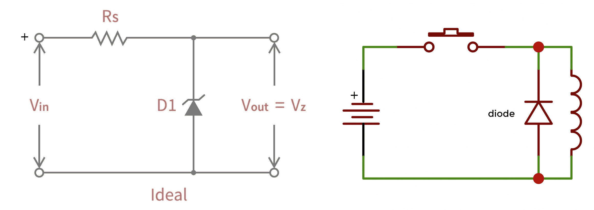
Zener on left, when the Vz (voltage, zener) is attained the diode starts to conduct. Drawing some of the load through the zener to keep it’s voltage at the zener voltage.
On the right full power is applied to the coil/diode. The diode doesn’t conduct with this polarity, so current goes through the coil.
When the switch opens, the field collapses and the produced voltage polarity is reversed, so negative is now at the cathode (top of the diode) and the diode conducts.
If you put the zener on the right, then apply full supply voltage to the diode, it will conduct at the zener voltage and pull the supply down to it’s value or burn up … probably the latter… Even if it survided this, it would not turn on until the reverse voltage rose to the zener voltage… more current more heat, bigger diode.
I have a box of 1N914 small signal diodes that I’ve used for years and are about a nickle apiece. I think I’ve stepped on more of them than I’ve used