New diode laser hobbyist here. I recently picked up the Sculpfun S9 and have been doing a lot of experimentation in order to learn more about how it performs. One thing I haven’t been able to explain is the significant difference I observe when I set different scan angles (keeping speed power, and line interval constant).
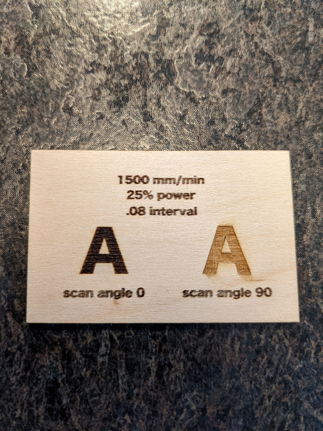
As you can see in the test below, when scan angle is set to 0, it results in a dark shallow engraving. There is almost no depth to it whatsoever. The horizontal lines are more clearly visible too.
However, when I set it to 90 it produces a lighter deeper engraving. Overall, I usually prefer this approach when filling shapes as the result is sharper and more interesting.
I am interested in learning why the results are so significantly different, or if there is something wrong/mis-tuned with my setup. Are all lasers like this?
My best guess thus far has to do with the fact that the laser spot is rectangular. Specifically a rectangle that is longer (with respect to x axis) than it is tall. So when the laser is moving across the X axis the material along the line spends more time under the laser “dot” since it’s moving parallel to the longer side of the rectangle. When it’s moving in the Y axis it creates a wider line that overlaps with other lines (hence the deeper engraving), and it spend less time under “dot” since it’s moving with the short side of the rectangle. This is all just a theory at this point, but interested to hear others thoughts here too!
grain of the wood. Try turning the wood 90 degrees and see if that affects the burn
speed. Depending on your laser and settings it’s possible that your laser head is never reaching 1500 mm/min in the Y direction. Do you have overscan configured? That would make it more likely that you’re reaching speed.
You are correct. The laser beam is not rectangular, and you are experiencing the effect of this. Additionally, the wood has also a direction of the grain, which comes into play as well. See some notes about this and other effects here: Settings guide - Diode Laser Wiki
Overall, the text in your image does not look very sharp, I think this should be better at the S9 (one of the best engraving lasers out there). It could be caused by the wood as well, but anyhow, make sure to check the guide here to set up the mechanics completely: Guide to mechanical adjustments and maintenance
PY, I had the same thought on the wood grain direction however I observed that I doesn’t fully account for the significant difference (color or depth). I do have 5% overscan configured as well.
Melvin, great spot on the text quality. I took at look at the notes you linked and ran though some of the mechanical checks. Turns out the belt that controls x axis (one with the diode on it), was too tight as it didn’t pass the 45 degree angle test. Loosening the eccentric nut and adjusting the belt tension seemed to do the trick.
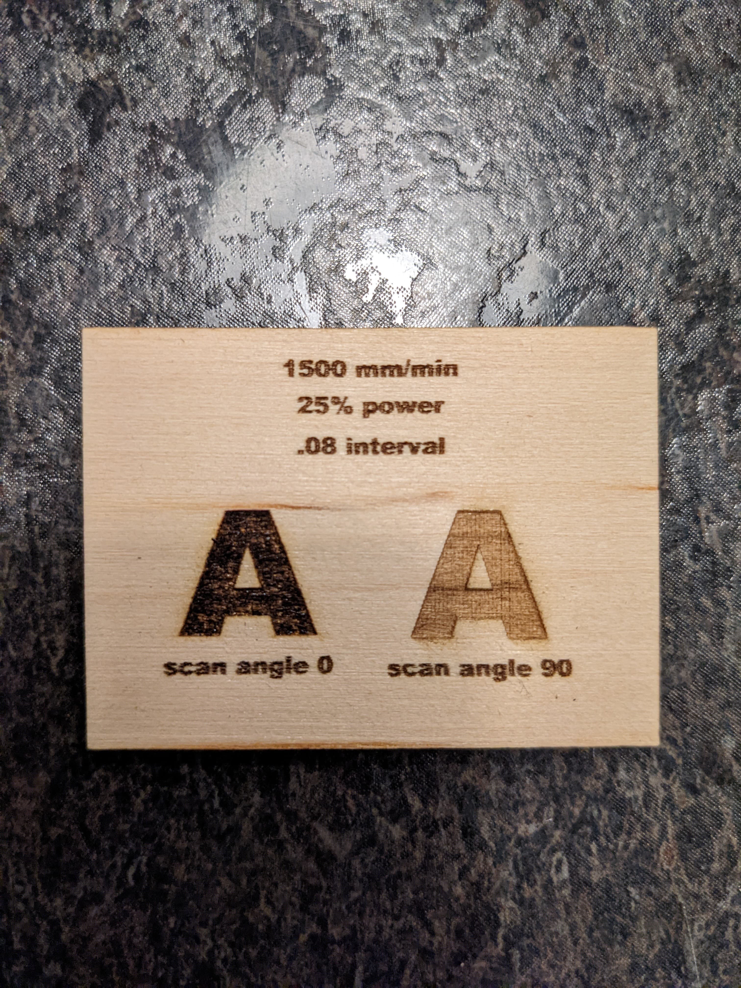
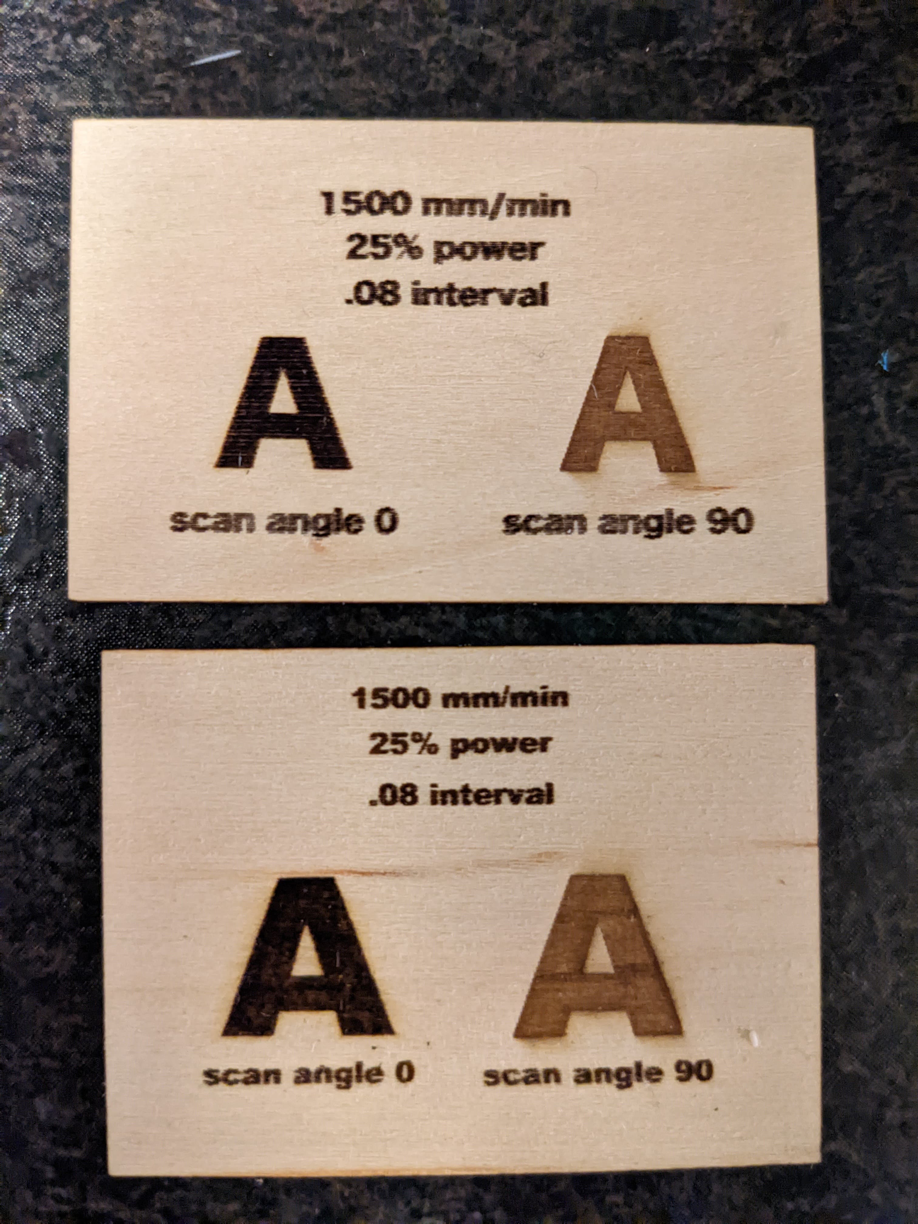
The results of this are seen below (after and also side-by-side). Unfortunately it’s not a perfect replication of the before as I didn’t save my original test file. You can tell that the label text is much more clear now (it’s even smaller than before). The “scan angle 0” example also appears to be much improved, a nice dark engraving with some actual depth to it now. The horizontal lines are much less apparent too.
Much appreciated! Not sure if I would have known something was up there.
Will also point out there is still a significant difference in the 0 vs 90 scan angle, but I am chalking that up to the “dot” shape at this point.
Try burning to a material with a more consistent surface to reveal even more artifacts. Anodized or painted aluminum is ideal but anything more consistent than the wood you’re using would help.
You may also be dealing with a focus issue but I suspect you should be able to get an even sharper output than you have there.
PY, ya I can give that a try when I get my hands on some more uniform material.
Though now I feel like I am running up against a different issue. Now that I have loosened my eccentric nut so that the x-axis moves more freely, I am noticing horizontal lines are now more wavy (doing my own interval testing to try to dial all this in). If I tighten it to the point of taking the play out of the diode, it restricts the movement of the x axis leading to jagged lines in my interval test. I just spent the last 2 hours trying to find that fine line, but haven’t been successful. Should I be looking at adding some scan offset adjustments to fix this at this point (keeping eccentric nut snug)? Could I be splitting hairs here? Also worth mentioning that I have the X and Y acceleration set to 250 mm/s^2 as mentioned in @misken notes.
That’s odd. Make sure the wheels are not out of round or otherwise malformed/damaged. Look into the grooves of the railing and make sure there’s no debris in there.
Run some tests on circles. If the start/ends of the circles meet perfectly then you’re probably fairly okay mechanically. Then yes, use offset scanning adjustment to correct for offset. Do make sure that you don’t have bad wheels though.
My personal opinion is that you can’t be too picky working out mechanical issues. Burn performance is so much about eking out every last bit from the machinery at hand. Software fixes should always be secondary or a known tradeoff.
Alright so I did a complete tear down the diode cage. Inspected the wheels, looked good no damage or deformities. While I was in there I also lubed up the bearings with some multi-purpose oil lubricant for good measure. Also did some finer adjustments of the belt alignment/tensions. I think I also got the eccentric nut in the right spot finally (very sensitive). After making those changes my interval tests in both directions were looking more well aligned and mostly straight (x-axis isn’t perfect, but good enough). Drew a circle as well and the start/end points appear to meet.
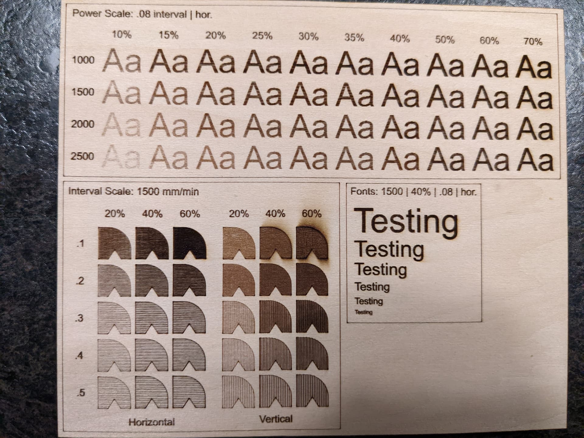
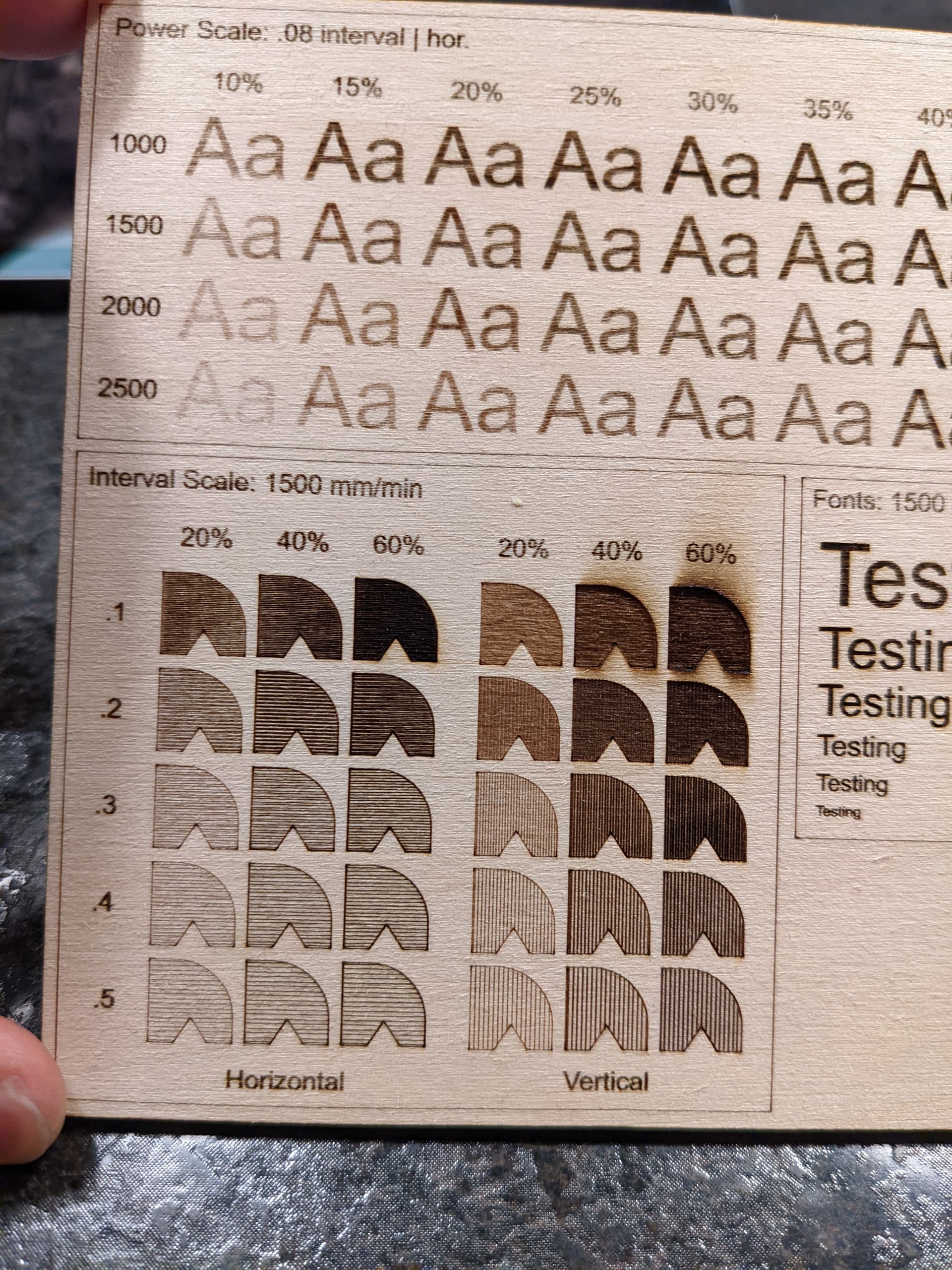
I also ran my material test and below are the results. This is done on 1/8" Basswood (as with everything I have been testing thus far). Open to feedback on how this looks to a more trained eye.
Overall I do still observe that a 90 degree scan angle provides a lighter deeper engrave, while the 0 degree results in a shallow dark result. Will probably stick with 90 for most of my engraves as I prefer the look it gives for my projects.
This looks to be dramatically better than your previous shots, at least from the level of detail provided in the photo. Well done.
As far as the interval scale it looks like on the horizontal scans that you have some room for even smaller intervals. Vertical scans looks solid at .1 mm. This confuses me a little because I had assumed you had a vertical bar for your focus dot. But this makes me think you have a horizontal bar.
Note that vertical scans will be slower than horizontal scans and potentially more prone to mechanical weaknesses since you’re moving a whole lot more mass. Just something to be aware of
Are you potentially using “Constant Power Mode” for your cut setting? I see burning at the corners of the box outlines. If so, I suggest you disable that. Alternatively, are you possibly configured to GRBL-M3 device rather than GRBL?
Ya the dot definitely seems horizontal. Not sure if that’s typical for diode lasers, the Sculpfun S9, or my laser in particular. Also good to know about the performance of vertical scans.
I also checked and it does appear that my device is setup as a “GRBL-M3 (1.1e or earlier)”. Can’t recall if I selected that during my initial setup or if it was something that was picked up automatically. Either way sounds like that is incorrect? Can’t say I am very well versed in the different device types, but probably should do some reading. Nice spot!
It will work obviously, but it’s not ideal or optimized. It would preclude your ability to use variable power to avoid burning during acceleration/deceleration.
By the way, I suspect if you decrease your line interval you could potentially get a better engraving at even lower power than your best vertical scan. Just speculating.
Ya that appears to hold true. I just have to really crank down the line interval to like .06mm (and power) to get the same type of deep engraving that a vertical scan offers at .1mm interval. It also ends be a little more sharper on the edges.