I use Loctite on pulley/shaft and grub screws. Leave it a day to be sure it is set. Not so easy when you need to remove it, but better than slipping. Carby clean helps soften it for removal.
That is pretty high, I’ve toned my acceleration down to 10 mm/s2, which is more gentle on the mechanics and not too slow. The hard acceleration will definitely loosen your pulleys. I have snapped two Nema 24 motor shafts with high acceleration.
10 m/s2 is about acceleration by gravity, drop a lump of steel and see if you can break something.
My stock acceleration on the Ruida was 6,000mm/s2 and 4,000mm/s2 for X & Y, respectively.
After changing out the head, I have my X axes set to 45,000mm/s2. That is down from 65,000mm/s2 before I noticed the motors (NEMA23) were getting way to hot… OMTech had the motor drivers set to twice the motors current.
10mm/s2 seems pretty slow, at least in comparison and the overscan must be great…
If you look at the total mass being accelerated, i.e. the carriage/laser or gantry, etc and the forces needed, the force on that little grub screw, stretch on the drive belt, etc.
Work out how a low acceleration affects your total velocity, change acceleration setting, load a job and check the total time,
acceptable speed for stress reduction.
When you do a scanning operation at a certain speed, the head cannot instantly go the opposite direction.
If the layer is set for 100mm/s it must speed up (based on the stored acceleration values for that axes) to that value then enable the laser. At the other end, it will slow the head to a stop, reverse direction and go back the other way accelerating up to the 100mm/s. This is overscan.
You can see the amount of overscan in the preview screen if you enable show transversal moves. Along with the extra time it will take to do the operation.
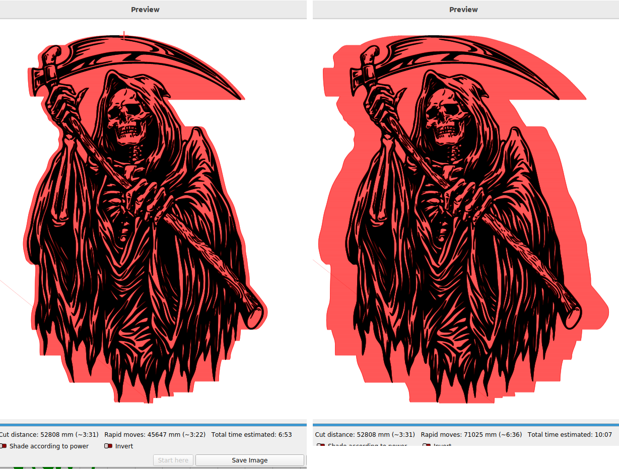
Here is a graphic with the acceleration at 40000mm/s2 then again at 6000mm/s2. The orange is the overscan. Notice the extra area the head has to move with a slower acceleration value. Also notice that the lower acceleration value requires about 50% more time to run the job.
I am using a GRBL controller with dynamic laser mode enabled, $32=1
The motion accelerates and decelerates to the end of the cut and doesn’t need to overshoot.
Your laser seems to only be on for constant velocity M3, then overshoots for deceleration, turn around and acceleration.
Mine does dynamic laser power M4 for velocity from max to stop, varying the laser power to ensure energy along the cut is consistent even with the machine stopped or accelerating. Lightburn has an option to not cut overlapping lines, which is one place dynamic power can overcook a cut.
apologies,
laser turned on
laser turned off
it’s all a matter of % power to laser, constant or dynamic
does your laser have a grbl controller or dynamic laser control in the same manner as grbl ?
Either you have some new fangled piece of hardware that I don’t know about or you have some misconceptions about how these work when it comes to overscan.
That’s why I gave a link to the grbl documentation.
I watch my router and this is what it does.
Does your router have a grbl controller ?
If so, is it setup for and using dynamic laser control ?
If not, you have to stick with overscan and the associated excess distance travelled.
Grbl calculates laser power based on the assumption that laser power is linear with speed and the material. Often, this is not the case. Lasers can cut differently at varying power levels and some materials may not cut well at a particular speed and/power. In short, this means that dynamic power mode may not work for all situations. Always do a test piece prior to using this with a new material or machine.
I know this won’t work on a tube machine, as most can’t lase below 10% or 20%.
This is machining, the proper speed (laser power) and feed (laser speed) for a material is necessary for a good result. You can’t run a milling machine at a slower speed (power) with a lower power and get the same results.
The power values of output are in the 8 - 32 bit range and can’t possible cover a linear acceleration of an object…
Also as they point out most materials are not linear.
It sounds good… it’s also missing a way to adjust it for a starting point and power… You can do this with a DSP… you can adjust the range of power applied…
laser starting point MIN_VALUE can be setup at compile time by changing #define SPINDLE_PWM_MAX_VALUE 255 // Don’t change. 328p fast PWM mode fixes top value as 255. #define SPINDLE_PWM_MIN_VALUE 1 // Must be greater than zero.
in cpu_map.h