Im using lightburn for a rotary spindle type engraver (kinda like a little cnc machine) and im doing nameplates, pet tags etc.
The machine was originally on a proprietary controller that failed, (and was a ridiculous price to replace) so I bought a marlin board and rewired the machine to make this work.
It works great for pet tags with Lightburn. But for nameplates ,I use this multilayered plastic that has a colour layer stacked on another colour and you cut through the top to reveal the inner colour.
My issue is that whilst doing line only looks fine, I want to fill the text.
I cant use regular fill as the Z height doesn’t change during the move between letters, so have to use offset fill (which I wouldn’t mind doing) but certain letters it drags the cutter on the surface between passes, its most noticeable on M and W but is not limited to them. As it stops the spindle but doesn’t retract Z for the move it ruins the workpiece.
Is there a way to set the software to do such a retraction? (It retracts properly between each letter)
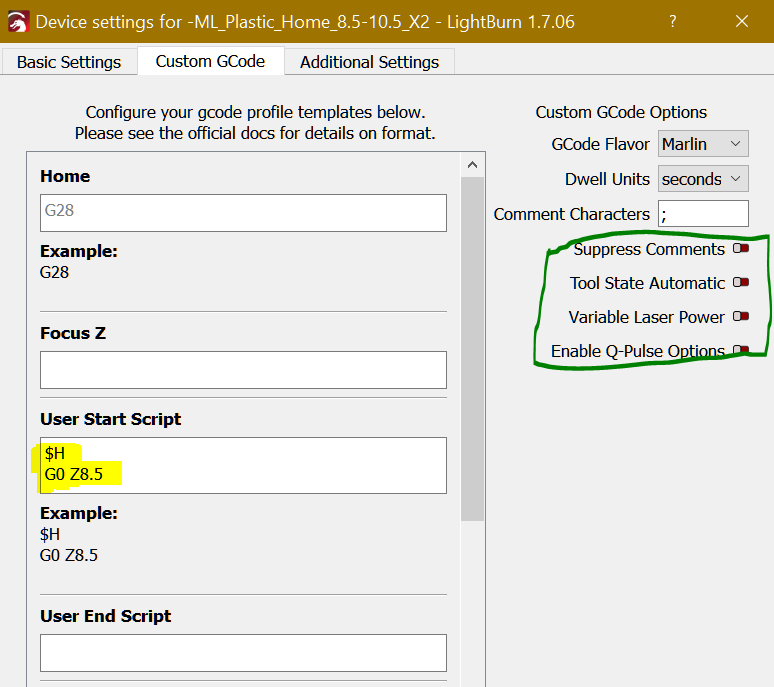
I read through this when ive been troubleshooting but unfortunately it didnt help. I have kind of figured a workaround but its not ideal as it hard codes the Z height into the GCODE settings. I figured that as the spindle turns on and off a lot I could add code to the Tool On and Tool Off GCode segments.
So for Tool On it is
M3 S{power}
G0 Z10.5
and for Tool off I have set
G0Z8.5
That way it jumps up 2mm for the moves.
Its not a good solution though as it means that to change the height you have to adjust these settings each time which whilst I could do it, im not the only user and doubt the others could do this.
My initial thought was to use relative moves for for Tool on
M3 S{power}
G91 //set relative mode
G0Z1 //Set the height 1mm lower
G90 //Set absolute mode
and for tool off
G91 //set relative mode
G0Z-1 //lift Z 1mm
G90// set absolute mode
But the problem is that whilst the first letter might be ok and it will let you easily input the desired depth it actually gets deeper and deeper the further it gets on in the code.
I tried a hybrid of the two methods, so tool on used absolute and tool off relative but the issue becomes that you are hard coding the height and its a pain for other users to change.
Is there a way for me to specify the height called for in the cut settings like how it gets the power setting? Is there a better way to achieve this lifting?
I have tried and failed at enabling firmware retraction in my marlin config as that would have been problem solved but whilst it enables in the config it doesn’t seem to enable it in software, unsure if this is a board issue (SKR1.4).
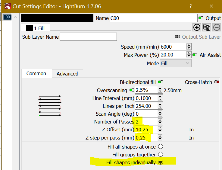
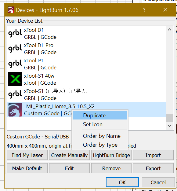
I was thinking of dividing the shapes of your projects into individual shapes so that, with a Custom GCode, you could define options per layer… But I think I understand your problem better and maybe it’s not necessary, I even think it’s a simpler solution! :
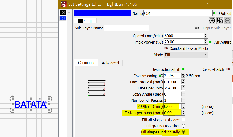
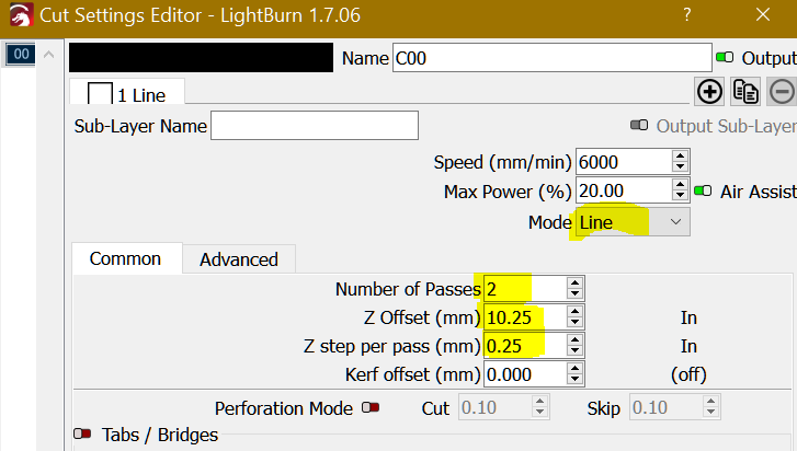
I was using the Z offset originally to set my depth and tried the z step per pass (although the biggest issue is im rarely needing multiple passes on this machine) but the z step per pass seems to go much deeper than I specify it to go so ruins the workpiece but also doesn’t sort the issue of the head scratching across the work, it doesn’t work like a retract command.
With the regular fill it doesnt lift the Z axis on each line so the area being filled ends up as a big gouged out area the height and width of the whole area.
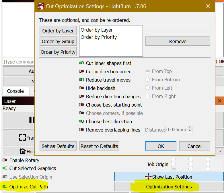
I have tried the optimization settings too including turning off optimization but it doesn’t appear to affect Z axis moves.
We are not 100% sure that the distance from the workbed or material is the same to the tip of the tool, so keep the first pass as a “levelling-surface-pass” then do the second and / or third (in baby steps) to the required final depth.
. Important:
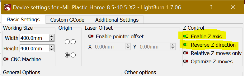
1 - Check if your machine Home cycle also homes Z and disable Auto-home in Basic settings, when you run a project it will Home then down to Z8.5 ( may not need this…).
2 - The above device will move up the Z between each shape with the above Cut/Layers settings.
3 - If you have different materials with different thickness just duplicate the device give different names and change the values accordingly.