Spots appearing at line intersections

What settings may cause dots to appear at the intersections of lines?


X-Y Test.lbrn2 (7.4 KB)

It looks as if the laser is pausing at each corner. Note: The vertical line on left is 3mm in length and the horizontal lines are 8mm in length.

DSP AWC708 Controller
LightBurn 1.7.07

min power being set too high can do this. As it slows and reverses, it’s not throttling back the power enough

1 Like

It must (almost) stop before changing direction, which means the controller must reduce the power as it slows to produce the same effect on the material. As @Dannym points out, the Min power setting for that layer is too high, so the controller can’t reduce the power enough at the lowest speeds.

However, ordinary DC-excited CO₂ laser tubes won’t ignite below about 10% of full power = full current, which means you can reduce the layer setting to the point where the laser won’t fire in the corners.

Amusingly, the firing behavior depends on both the Min and Max power settings, the cooling water temperature, and the laser path through the pattern.

The results I got while destroying CDs may be of interest.

With Min = 7% and Max = 10%:

With Min = 7.1% and Max = 10%:

With Min = 8% and Max = 10%:

Bottom line: You may find settings that work today, but they probably won’t work tomorrow.

3 Likes

Thank you for your support. I will give that a shot.

My 90w won’t fire below 18%; that is another issue​:roll_eyes:. Maybe it is time I modify my laser to add a 40w laser tube in parallel :rofl:. If you are curious, you can see it at www.timsmachines.com.

Yeah, 16-ish W will cook the corners, fer shure. :grin:

That’s a mighty fine machine: nice work!

1 Like

What matters MOST is the PWM freq. The power supply and tube basically have a minimum pulse width needed to get output.

The power supply and tube needs about 1ms to turn on or turn off fully.

People keep setting the systems for like 10khz which is insane. That destroys the low power range as it won’t output for 20ns pulses.

You can also set the pwm even lower than the tube response, based on your speed and spot size (spot size is usually about 0.2mm for 2" lenses). Total turn-on and turn-off of output with an RF laser still yields a smooth cut if you get in two pulses per spot.

HVDC-excited tube is ramping up and down within 1ms, not an on/off pulse. If you PWM at about 700Hz, you will get a very nice linear response and smooth cut up to about 400mm/s, at which point the ramping up/down stretches past the spot size and the cut width ocsillates. If you go faster, the cut becomes dots or dashes. But almost no case vector cuts anywhere near 400mm/s, only rasters do. Set PWM higher for raster. The tube’s response will end entirely at about 1.5khz-2khz. That is, the tube’s output doesn’t even ripple at 2khz 50% pwm, much less turn on or off.

To do a linear tune, first set the pwm to like 700 or 1000 hz, put paper on the bed, do a cut speed of like 50mm/s, then find the lowest power % that makes the laser actually fire. It’s paper at 50mm/s so basically any tube output at all will mark or cut it.

Enter that PWM AND like 1% below that %min power you got into the Ruida config (not user settings). This creates the linear tune and you generally can, and should, to set min power at 0 for everything in user settings, as the user settings scale within the min and max of the Ruida config. Everything vectors trouble-free without fiddling with settings further except setting speed

You will override PWM to higher if you’re above 400mm/s (usually raster). 2KHz is generally a good number. Like I say, the output doesn’t even ripple for 50% pwm at 2khz. But there is one technical catch- the Ruida does not resync its pwm to the job contents, nor does the “right thing” and compare the pwm counter to the design demands at that moment. At 1000mm/s, the 2khz pwm cycle is 0.5mm spatially. When the head crosses an edge in the design’s graphics, it may be at the start or end of that 0.5mm wide cycle but it’s not going to start to fire until the next pwm cycle, and when it reaches the edge of the graphic, it also will stay on until a new pwm cycle starts.

also machine parameters, esp acceleration, affect the corner cut quality quite a bit.

if your machine is rigid enough to run high acceleration, then the physical length of the segment of a vector where it’s not at full speed and has to use power scaling can be so insignificant that it may not matter what you do with min power

the ruida has several poorly documented controller parameters that handle cornering behavior and allow you to run much higher accels and maintain cut quality

there is a field that is seems to limit the derivative of accel, aka “jerk”, and that will prevent overshoot and “ringing” or “bounce” to test for that you actually just need to make a tiny radiused corner because it performs a stop on a regular corner and that type of motion is generally immune to bounce, but tight curves are what you have to tune for

AFAICT, for DC-excited glass-tube lasers (which is what I think is in that fine machine), the PWM demodulation filter in the power supply has a 200-ish Hz cutoff frequency, so the tube current won’t see pulses under maybe a millisecond.

From what I’ve measured, this is 50% at 2 kHz:

The cyan trace is the PWM signal and the green trace is the tube current at 10 mA/div.

This is 50% at the usual 20 kHz:

The tube current is smooth at about the 17 mA average of the ripply 2 kHZ version.

The 20 kHz PWM carrier frequency eliminates the ripple around the intended output, so the effects you’re seeing for low PWM carrier frequencies may be due to the interaction of those ripples with the material.

At carrier frequencies below the 200-ish Hz demodulation filter cutoff, the power supply interprets the PWM signal as a square-wave analog input. This is 30% PWM with a 100 Hz carrier:

The notion of definite rise and fall times may not have much meaning with those waveforms. :grin:

The filter demodulates the 20 kHz PWM into an analog signal to control the tube current. The power supply responds the same way to an analog control signal, so the filter really does eliminate the PWM before the current control stage.

What the current controller does see is the demodulated value of the LightBurn (or whatever) layer power settings, with rise and fall times in the millisecond range because that’s what comes from scanning across the design’s geometry at a few hundred mm/s.

However, the tube current still does not have a clean rise or fall time, particularly for low power levels. This is 10% PWM (with 20 kHz carrier) across 1 mm bars at 250 mm/s, with the green trace at 5 mA/div:

The current looks more like a pulse at 80% PWM, at least after the initial damped oscillation:

That’s what I thought, too, then I tried some corner radii and found tighter turns worked better for the default Cut Parameter values:

As a bonus, it seems none of the obvious (and undocumented) Engraving Parameters had any effect on an actual engraving:

I’m beginning to think much of our hard-won “common knowledge” doesn’t survive close inspection.
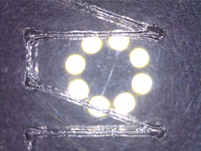
The “Engraving Parameters” quite definitely get used during rastering. I can’t quite figure out why he’s not seeing it but they do get used… they have to, the machine has to get its numbers from somewhere.

Try a very small (~0.5mm) radius on the corners of a square. Run at high speed, like 100-200mm/s (paper would be a good choice of test material) and make the square large so the axes will actually get up to speed.

Making the corner radius small just makes it more obvious. Really you don’t even want to be able to see the actual radius, we just want to trigger the Ruida’s curve handler instead of a vector series.

The ringing in your third column is that. Go into Ruida config and adjust “Speed Factor”. This parameter comes at a cost of overall speed for curvature cuts so you want to tune it high enough to make the ringing disappear or at lease make it very small.

You may want to go back and see if you can increase acceleration to speed up jobs overall. Also, issues with “min power” being too high or too low has less effect when the accel/decel distances where power will be scaled back are shorter

Absolutely, but changing the Engraving Parameters changed nothing in the results, so they’re coming from somewhere else. :exclamation_question_mark:

I’m in the middle of something else, so it’ll be a while before corner tweakage comes around on the guitar again. It definitely needs more puzzling, though, because I’d like even little squares to look better.

Too many digressions from the main topic already! :grin:

This topic was automatically closed 30 days after the last reply. New replies are no longer allowed.