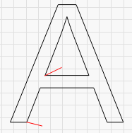
Hi there, have you anybody found out how to do some “starting line” for stabilising the laser beam, before it cuts the part you need? something like (the red lines):
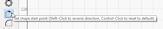
Anyway, I didn’t find in the documentation, how to use “Edit start point” tool - there’s the note "these tools are covered in ‘creating vectors’ in more detail, but… there’s nothing. I’m trying to reverse the direction of the cutting vector, but I cfan only change the position, not the direction.
Thank you! That’s great. Anyway, that’s for the whole layer, isn’t it? So if I need various angles/length, I should to use more layers, if I take it clearly… That could work, thanks.
You can also manipulate the starting point by using the Start Point editor, and adding nodes with the node editor if you need to. That would let you start in the middle of a straight line, where the entry angle is easier to work with.
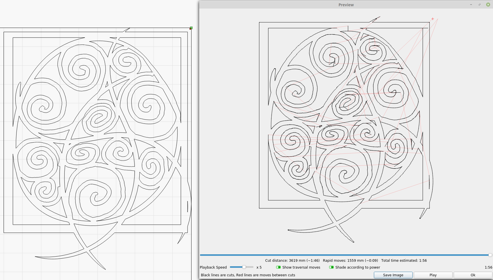
As you can see, some “art” is quite difficult to burn.
My idea of lead line is:
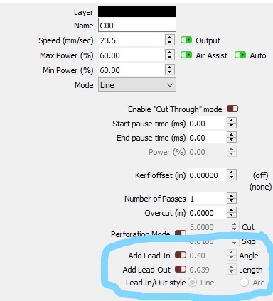
choose a node of the object and the length of the lead line
use “default” angle, but you can choose the angle (and also the length) individually to each object (just drag the other end and turn it around)
the lead line could be displayed as a dotted line or something (another color, whatever) and can be turned off/changed globally/whatever
you can choose at the layer dialog, if you want to use existing lead lines, or redefine them globally (as it is right now), or not to use them
The advantages:
for persons using LB - individually or globally defined
for SW - you don’t need to recalculate the cutting plan every time you modify one (or more/all) lead line
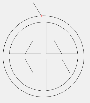
About the function right now: it’s quite unpleasant I can’t choose another angle than -90 to 90 degrees - it’s really hard because the sw can’t recognize, which part I want to “save” and which part goes to the trash bin, and sometimes the choice is very difficult. For example, I tried to make the cross for beam setting, and the 90 degree angle was THE ONLY USABLE selection, but not ideal… just try it yourself. krizek.lbrn (25.8 KB)
(and I had to make another circle around, just because LB can’t recognize the inner/outer shape - but I can accept this).
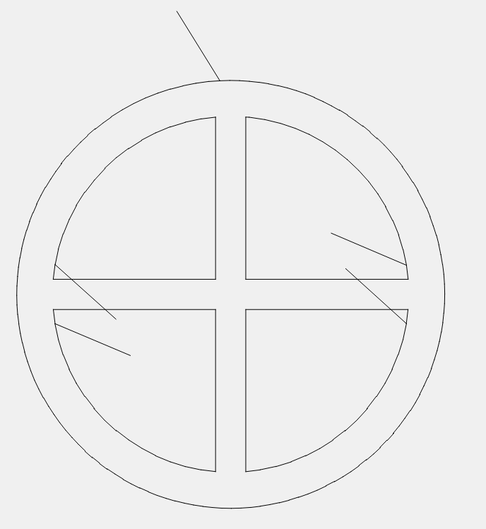
I think the trouble you’re having is because of the kerf setting, and how it interacts with start points. I was able to easily do this by inserting a vertex in the middle of the lines and setting it to be the start point:
However, when kerf is applied, it offsets the shapes, and the result is reconstructed, and that extra node in the middle of the line is removed automatically, because it’s redundant, so the nearest point is used instead, which isn’t usually what you want:
I’ll have to look into this - I should be able to detect this case and re-add the missing node to the resulting offset, which would make it much easier to use the start points with kerf.
make own nodes for leading lines
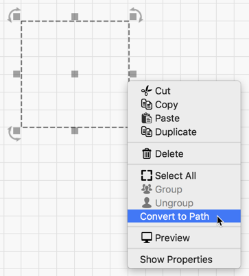
…this remainds me: is it possible to make my own nodes at predefined shapes? I tried to insert node to the rectangle, but didn’t succeed.
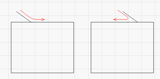
I can’t understand why you’d want to - The point of having a lead line is to allow the laser to get up to speed so the power is applied evenly. If you have a 90 degree entry line (or greater) your laser will do a full-stop when it hits the corner, completely removing all benefit to having that line there in the first place.
You want an entry line like the one on the left, NOT the one on the right:
Yes, but you have to convert it to a generic path first. (Edit > Convert to Path OR Right-click for Context menu)
Interesting idea, I’ll try to do it this way.
Anyway, just in theory: Sometimes may be better to slow down and change the direction, than start to burn the beam at the point - it makes quite big holes to the metal, etc etc (and that’s the reason for the leading line). The sharp angle may burn the inner part, but you can be interested at the outside part, so let the inner part burn at all, never mind.
Probably depends, if the angle is just “a little bit greater than 90” degrees, or “almost 180 degrees”. And, of course, depends on results you expect.
Anyway, I’m glad that there’s still some way to do it ‘clear’ with the inserted node.