I had the Ultimate Air Assist connected to my laser for a few weeks. Loved it.
I was hoping to allow the relay to stay open for 30 - 60 seconds after I ran a job, so that the exhaust and air assist could clear out, by adding a large capacitor to the relay. Worked like a charm.
However, I must have done something wrong, because now the voltage from the status and 24v wires to the relay remain powered at 12v, with or without the capacitor, and so the relay will not de-energize.
Before a run, I measure 0v from the Status to Ground, and 24v from Wind to Ground. Then when I do a run, and it ends. I get 12v from Status to 24v pin, and 12v from Wind to Ground.
Yes, I had the diodes connected correctly, but I don’t know if they got damaged while I was fiddling, and the damage was done, and now a diode won’t matter.
Good new / bad news. Those outputs are optically isolated. If you did screw something up, it’s just those outputs.
Those outputs switch the ground, not the positive. Factor that into your diagnostics. When active you should have voltage between the terminal and positive. My only other suggestion would be to measure to the pos and neg on a different terminal. Baring that and you wanting to risk it, you have the second laser tube outputs, but they are 5V, not 24V. Theoretically the second laser set to 100% would et you 5V on that terminal.
@Dave01, do you know where those optocouplers are located, or where I can find the information on where they are? I have the board apart, and it isn’t obvious where they are.
I know one of the guys on the RDWorks forum tore into the controller some time back. You could post a question there.
I have never opened the box so I couldn’t say. You might get lucky enough to be able to swap the ones for the Out1 & 2, or snag the ones being used for the CN2 terminals if they are the same. Just tossing ideas out there. I do know they are only rated for 500mA, so I would bet your capacitor overloaded them.
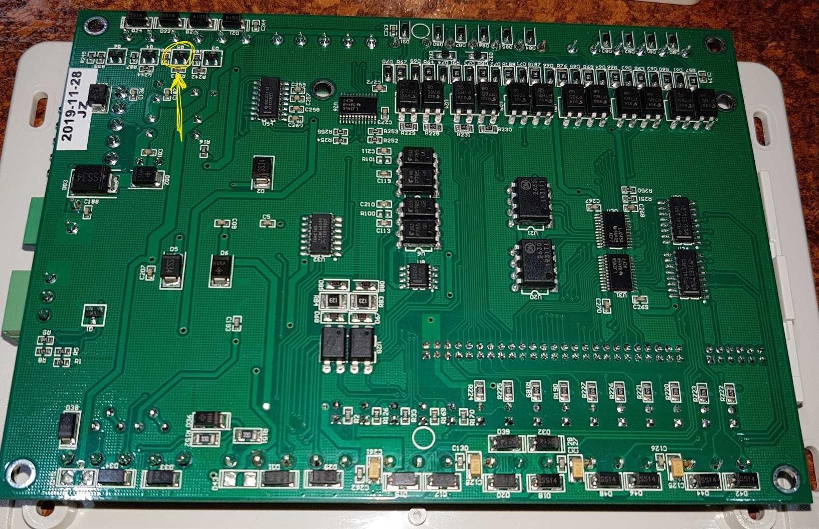
If you’ve got it open, post a nice focused decent resolution photo of the board and I can probably locate the optocouplers for you. And I’m curious what they look like inside.
The component I have circled (in position Q5) is the item I think has gone bad. I actually now believe it is a transistor, not an optocoupler.
I am getting different readings from this component compared to the ones next to it.
@Hank, yeah, that is what I thought too, after I did some more web image searches. Not sure how to test them to know if they are still any good. Ideas?
Would you agree, that if the component I circled is getting different diode and resistance readings than the others next to it, that it is bad?
That is expected. As @Dave01 mentioned, CN1 switches ground. CN1 pin 4 to ground should always measure 0 volts.
I do not understand how this is possible (see above / these pins all switch to ground). If you are truly measuring any voltage across CN1 pin 5 (wind) and ground, there is a problem.
CN1 pin 4 (status) / ground to pin 6 (24+) or CN0 Pin 2 (24+), if you are measuring only 12v, there is an issue…
Here is what I think overall is your issue:
A capacitor is for use in an AC circuit. In a DC circuit, it will act as a resistor / block.
These two videos might help you understand why adding a polarized cap to a DC circuit requires some understanding of the resistance in the load (in this case your relay), where in the circuit the cap is placed, and the voltage in the cap (both upon charge and discharge).
I can’t really help you, except to say I did something very similar. I ended up getting rid of my capacitor and replacing the board. I’m not really an electronics guy, and wasn’t sure what I had done to mess things up.
Good news. I’m working with some beta versions of RDWorks, and one of the features being worked on is a start and stop delay for the STATUS terminal. I don’t have that one yet, but I’ll keep you in mind when it pops up.
I’m looking at putting a relay for the exhaust blower on the status output. At first they were talking only an off delay. But once I explained the advantages of having both a delay between status and job start as well as the off delay… ‘Oh, no problem.’
They have a number of nice little things in the works, and that’s all while the new multi file program is under development. I half expected them to say sorry, that will have to wait for the big program, but they have been really responsive to some of the little tweaks. Something as simple as having a perimeter run option for the go scale instead of just the box outline.