I’m working through various issues with an imported orange & white Chinese 130w
The build quality is as expected… which I’m fixing.
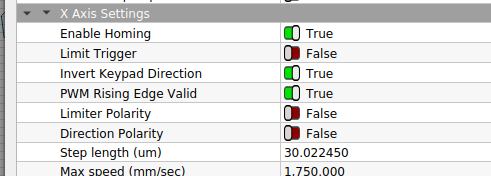
My latest issue is confirming that the machine settings are correct for the stepper motors… they seem as if they haven’t been ‘tuned’ to the motor.
In particular I’m getting wavy lines at the start of a cut, which I’m convinced is due to acceleration speeds. I’ve altered them and seen some improvement but I just don’t know what to set them at…
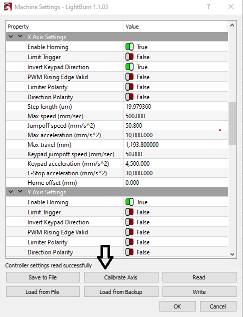
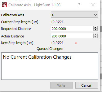
Just went through this! Found that adjusting the x and y start speed under the engraving parameters got rid of the wavy lines at start of engravings. Do your steppers have encoders on them? If so trying setting to 2000 steps per revolution and run the calibration routine. before hitting calibrate axis draw a 100mmX100mm box, cut it out of some thin ply measure it then go into the calibrate axis. enter 100mm for requested and measured value for actual, it will adjust the step length automatically. Otherwise you gotta crunch some numbers.
Formula:
step per inch = (motor steps * microstepping) / (travel at one turn of the motor in inches)
if microstepping is set at 16 (1/16 on the driver) then and you are using a sprocket and chain with a pitch of .25 inches and 12 teeth on the drive sprocket
= (200 * 16) / (12 * .25)
= 3200 / 3
= 1066.666 steps per inch
For lead screw that has a travel of .5 inches at one turn like the 5 start 1/2 inch lead screw and using 4 microsteps per step (1/4):
= (200 * 4) / (.5)
= 800 / .5
= 1600 steps per inch
Some steppers are ‘closed loop’ and can detect a step or movement failure. These have encoders on them to count the movement. I think this is what he’s referring.
@Bachman nice to come up with the math… Thanks, something I’ve been missing.