Hi,
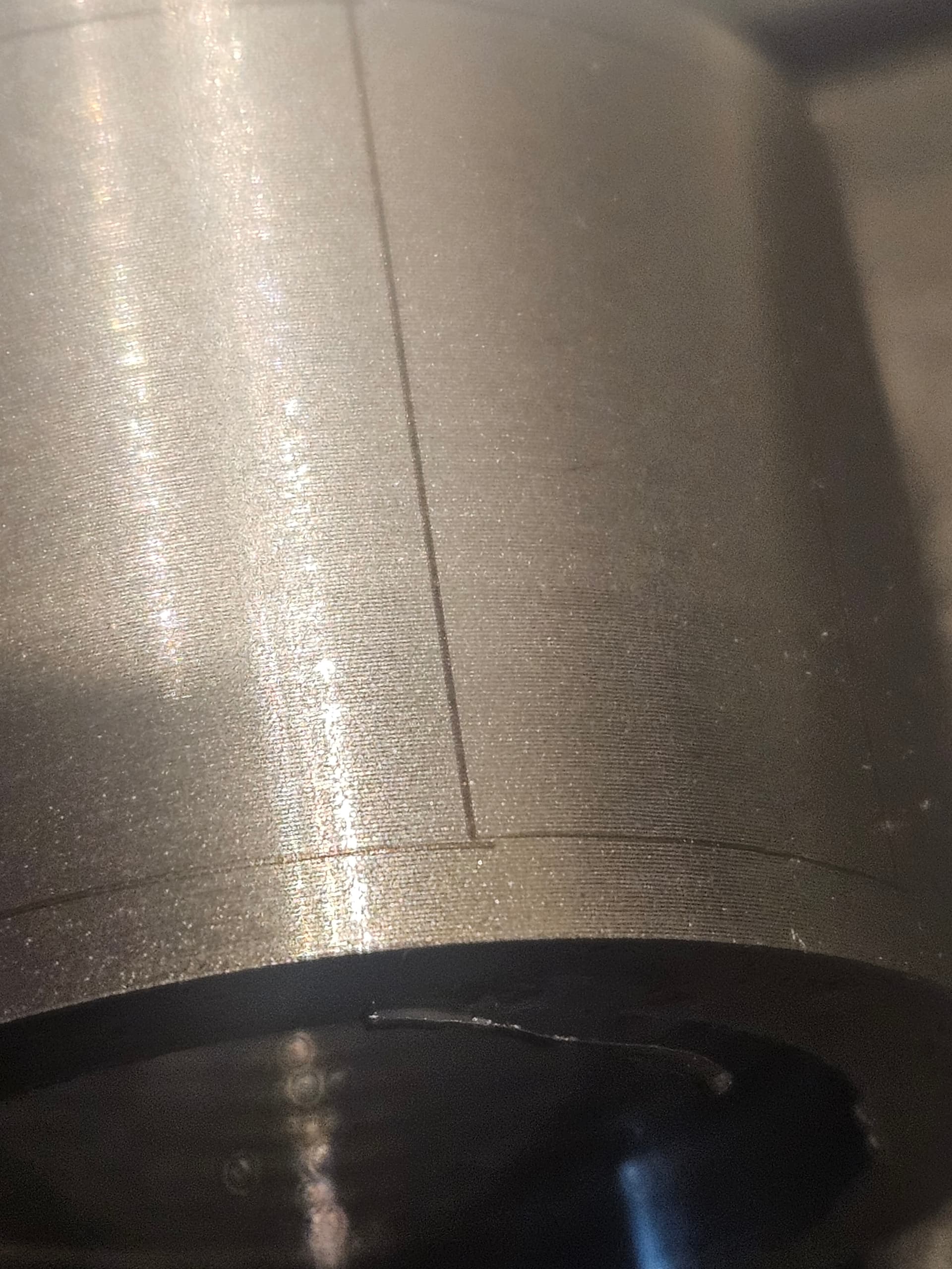
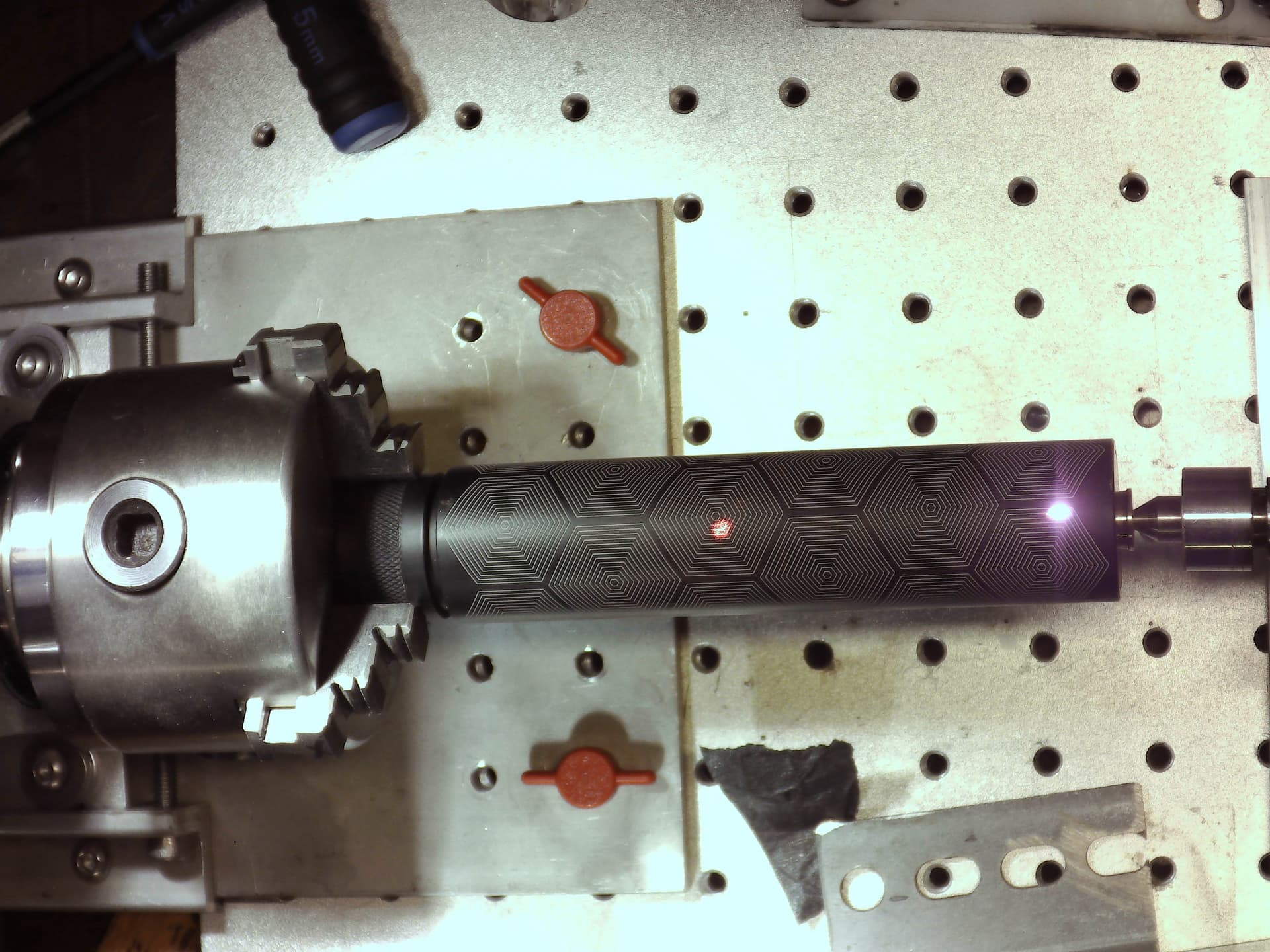
I’m running some SS rings on my G2 50W laser via a rotary attachment and I’ve run into a problem. When the rotary indexes it always leaves a staggered overlap like shown in the image. The overlap is set to 0.0 so i can’t reduce it anymore. My split size is exactly divisible by the steps and circumference, but still, there’s either an overlap or misaligned splits.
Has anyone got any advice on what it causing this or how to fix it?
It looks like your axis isn’t square with the galvo.
So like you said, circumference divided by steps, and you make your line interval divide equally into the split, the last tweak to mimic a negative value in the overlap is to slightly reduce the diameter. Leave the other settings alone. The stepper will move each slice a little less. Doesn’t take much. So fix your alignment and then try tweaking that.
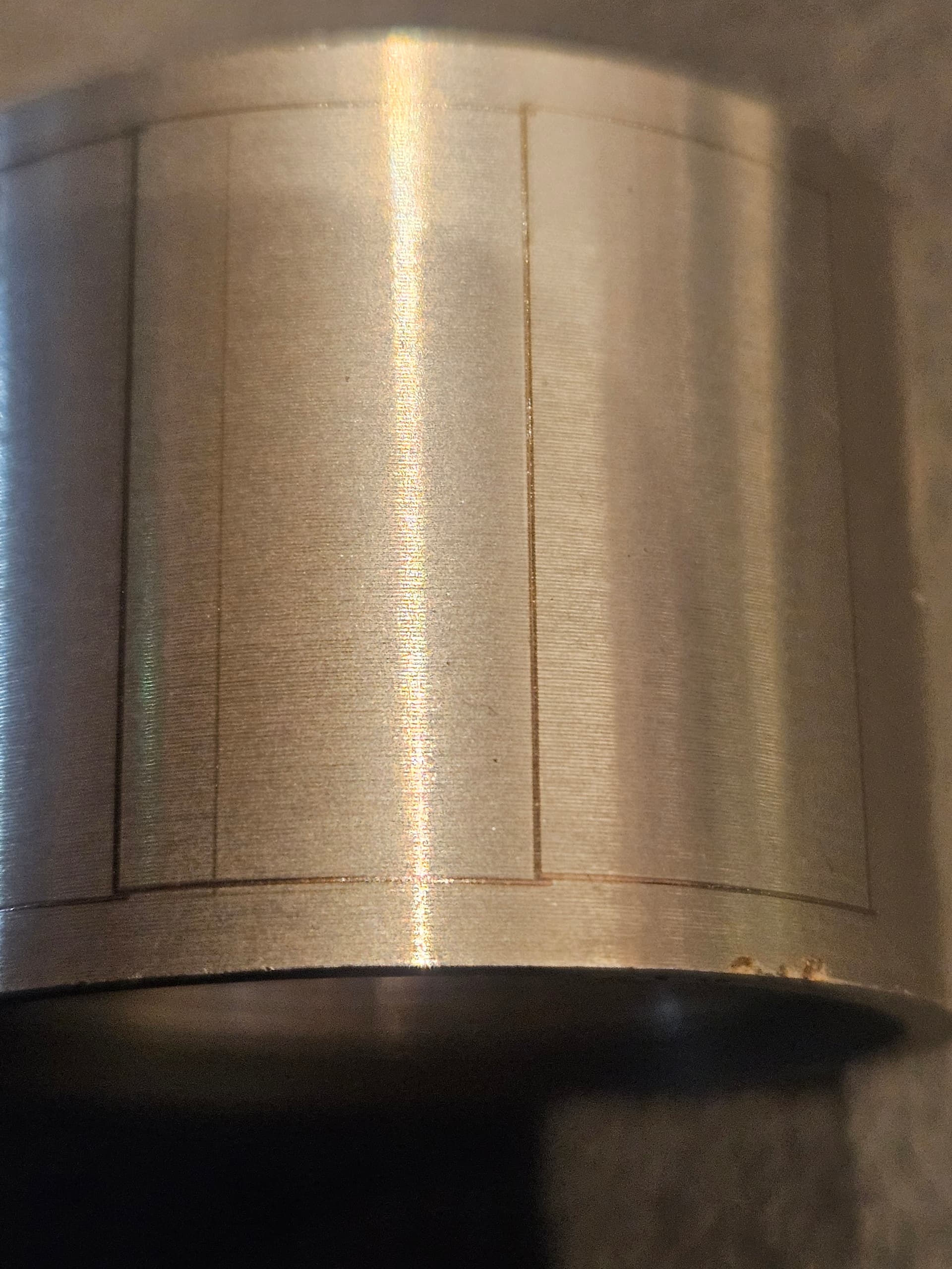
Interesting. Looks like you design is just a fraction higher on each square from left to right. Is it three separate boxes or one box with two dividers?
Higher on one side, lower other side.
Out of square with galvo.
1 Like
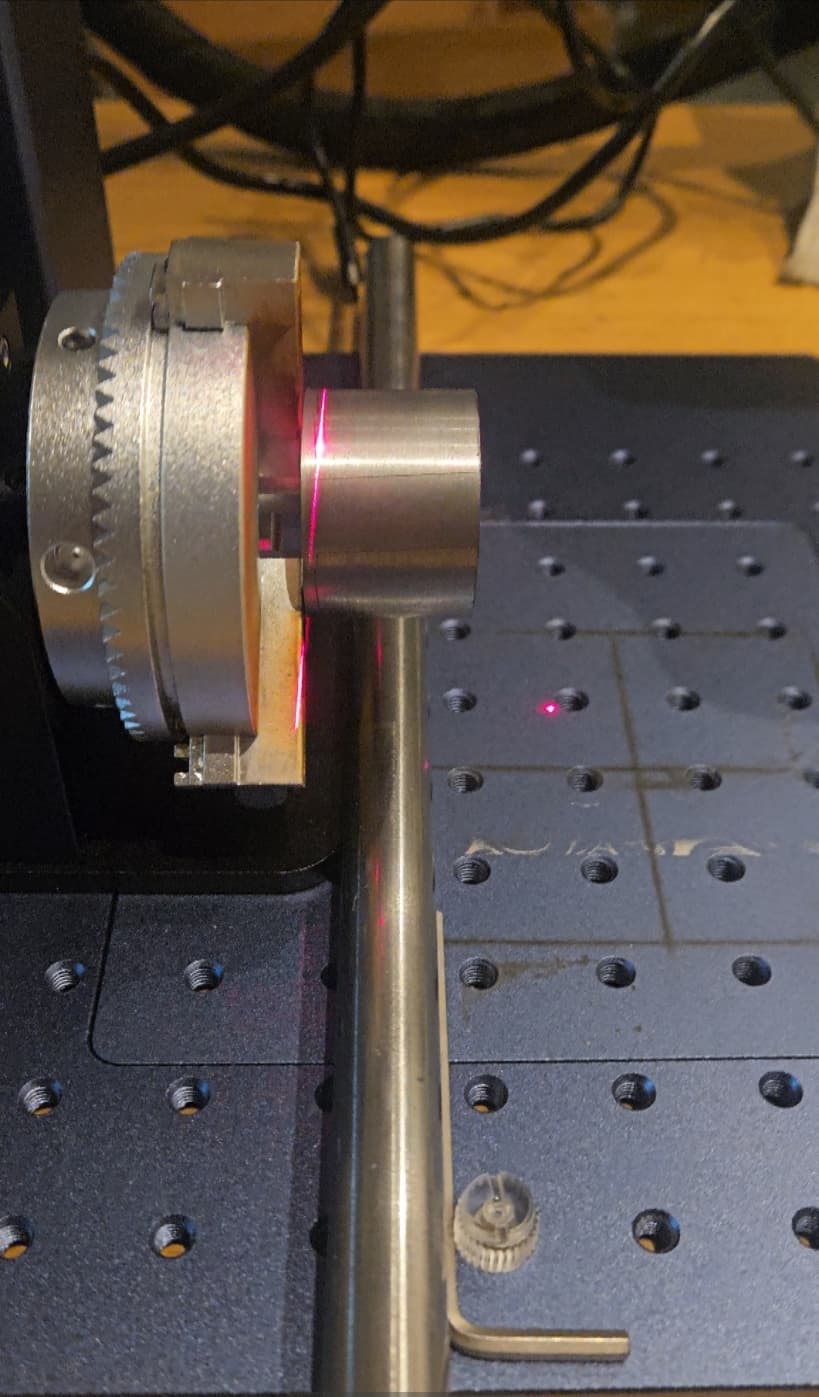
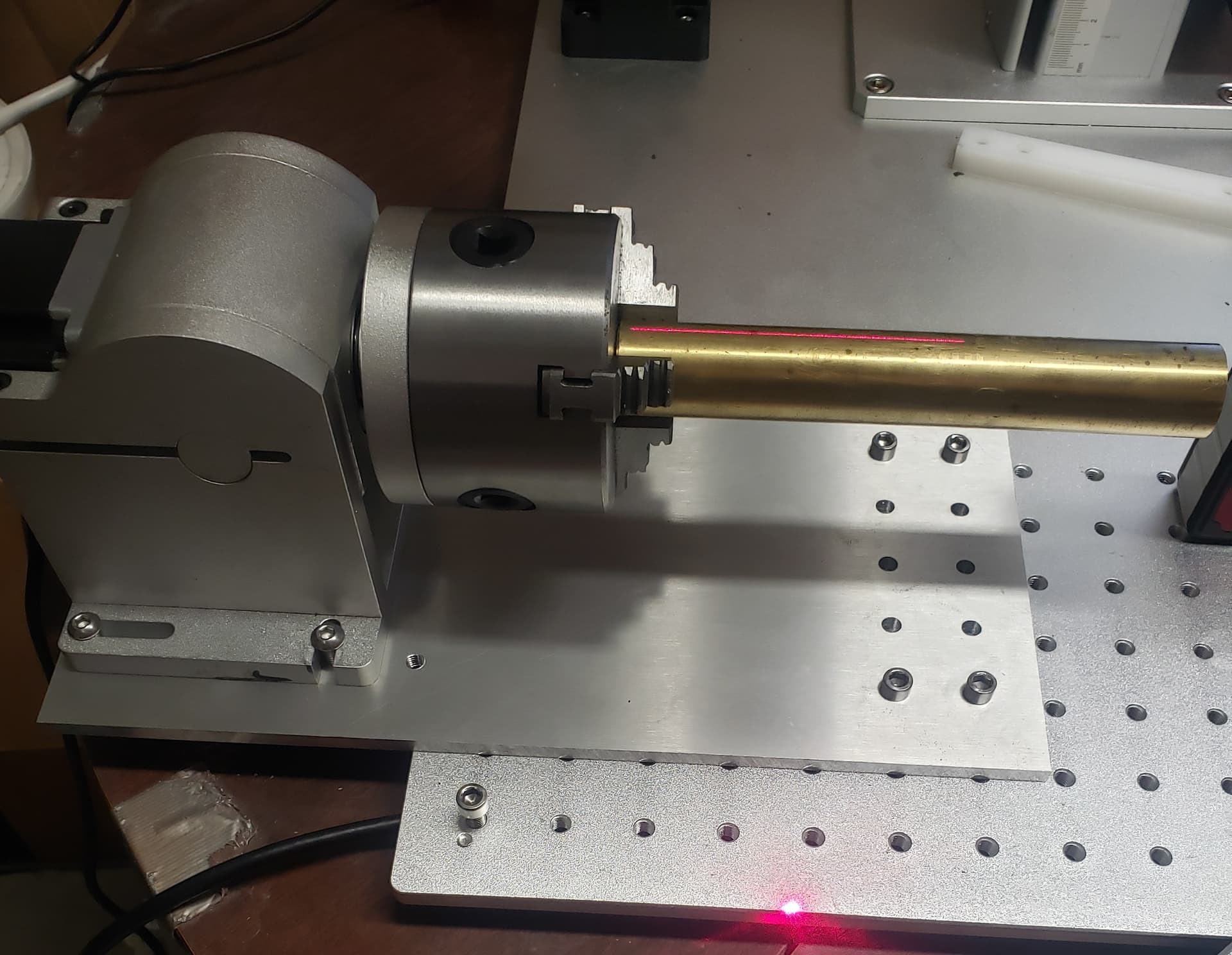
The chuck out of square definitely seems to be the case. Recfying it, though, has been a nightmare. I currently have two screws screwed into the base of the laser and a precision ground bar between the two screws then the chuck body butted up against that. This is completely square to the base of the laser. However, I did run a new piece and managed to get it 95% straight, but I had to off set the chuck with a 2mm spacing on one of the contacts of the screws.
The first image below is how the laser sits when sqaure with no messing around. But leaves the stepped result.
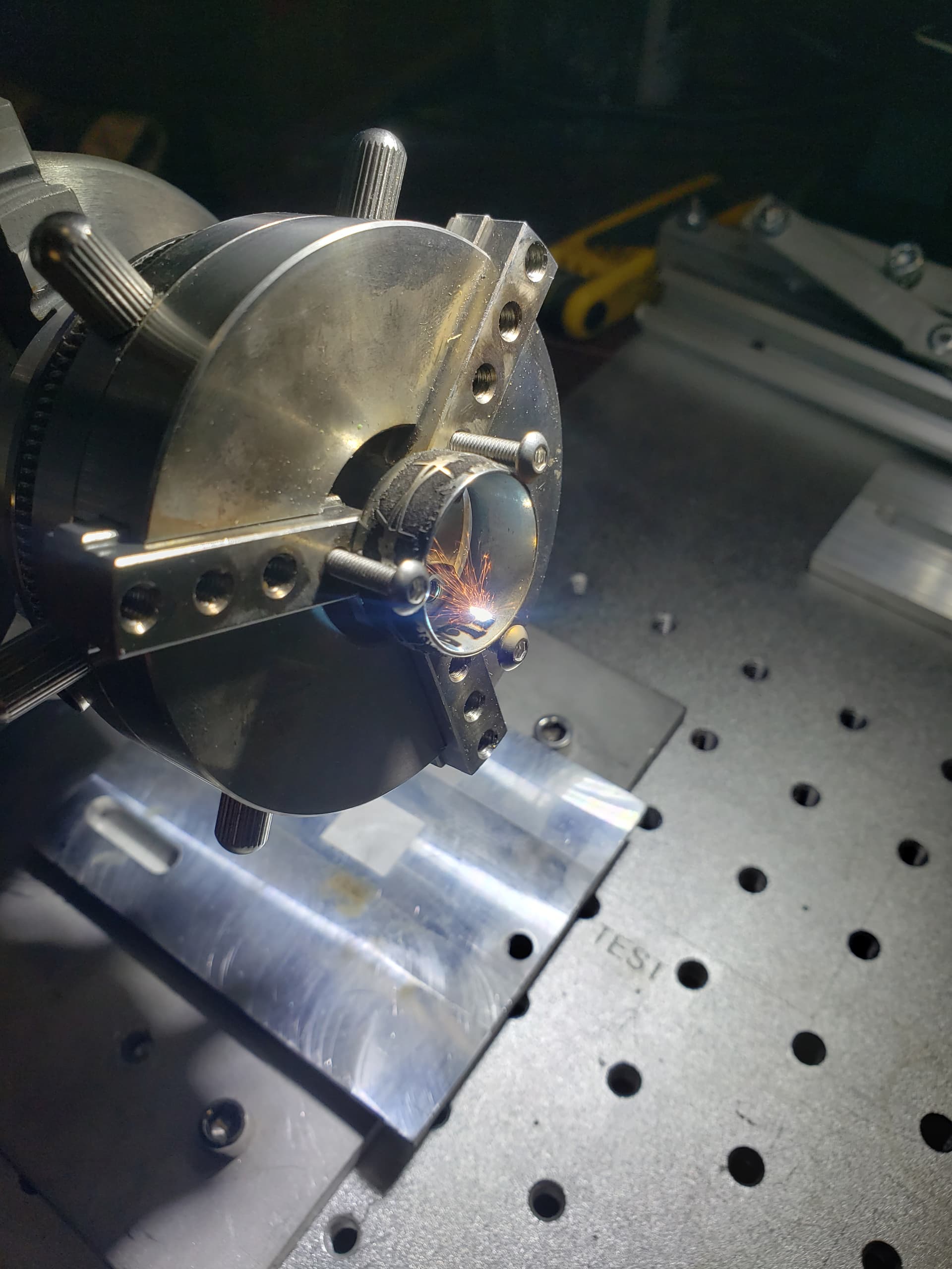
The second image with the allen key is the offset I had to do to get the engrvaing somewhat straight. You can see by the tilt it’s significantly off.
P.s the reason the chuck is off centre is because the removable plate has a dip in it, so I wanted to make it as consistent as possible by indexing it off the main frame of the laser and not 50/50 between them.
Any input on what I can do better would be much appreciated
Great info. Going to do this. The ID is 33mm so how much should I deduct if I have 10 even sections?
I would chuck a 3 or 4" long bar and frame a box same size, remove one screw. Maybe slot the hole with a round file but 1 screw should get you going.
Try a couple mm at a time on the diameter thats going to be for you to find out.
So just to clarify. Use the framing function of the laser to centre the rod that’s chucked up. Leave one screw as a pivot and the other to adjust and lock?
Sure, that would work.
Also once you move the rectangle around make note of the position when it aligns, that will be your output center.
I’ll give it a go. The issue is that there’s no way to mount the chuck to the to laser. There’s a slot that has been milled into the base to take screws. But that slot is directly under the chuck OD and there’s only about 2mm of clearance so zero room for the head of a screw. Let alone a way to ajust it and save the position.
Also, do you think i should move ot back into the center of the laser? I noticed when making adjustments that the side of the part closest to the centre had a much eaiser time of coming in true than the farthest away point.
It would benefit you to be able to screw it down, but not 100% necessary. I made a plate out of 6mm aluminum that screws to the rotary and extends out past the chuck. Solid mount with the added benefit of being able to cantilever the rotary off the edge. You could screw it up from the bottom with countersink screws and a nut slipped into the 2mm area you refer to maybe. Or maybe pull the chuck off, mount to a plate, reinstall. Sounds like you have some messing around to do. With a galvo having your rotary under center is key. Repeatability is key.
Hat’s off to you, 1000% doing it right in my opinion, getting everything dialed in and working properly before you start with the good stuff. From following a lot of posts you are in the minority.
Couple mounting ideas:
Great info man. I’m going to follow your advice. I think a plate I can drop in and out / on off is the way to go. Then set and forget. I run a CNC shop so I know how critical set up is. It saves me second guessing myself later. Then I can’t blame my tools. Not a position I like to be in. It usaually gets expensive at the point…
Thanks again. I"ll keep you posted on this.
1 Like
Sounds like a good gig.
I’m just a hack with a bunch of machines.
Anyone reading this back the rotary out of alignment was the problem. I managed to manually align the it to do some tests. Currently waiting on an 8mm sheet of aluminum that that can bolt on and off the laser bed so I can just leave the rotary set up.
Thanks for the help ![]()
1 Like
Mine is pretty basic but I’ve seen some with slides built in, etc.