Hi guys. First off a simple question. I am using the Edit Nodes feature… my simple question is what is the significance of the green vs red nodes?
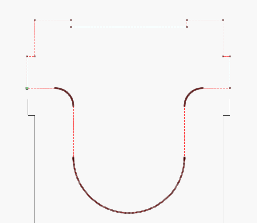
My more complicated question might be a hard one. I am going to take several screenshots to help explain the issue. First off, the object I am editing is a fairly simple one:
Now, I am going to explain what I was doing and why, just in case I am doing something wrong or there might be an easier way. Will also help to explain the issue
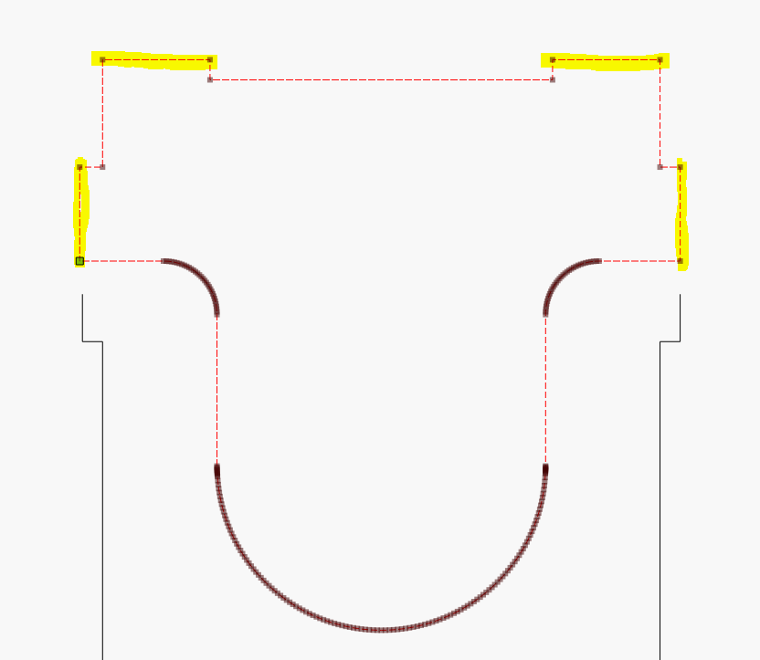
Some portions of this object have extrusions that are 3mm, intended to be the tabs that fit around other - it was designed for 3mm plywood. The issue is that the wood here where I am at is actually 3.4mm thick and the tabs are just a little off… and I am trying to fix that. To that end, the highlighted pieces need to be extended outward by .4mm:
Ok, so… to do what needs done, I usually break the 2 nodes on either side of the edge that needs moved, and I have my arrow key set to move .4mm… so just one nudge up, then I drag the nodes below and snap it back together. Its really quick and usually works really well.
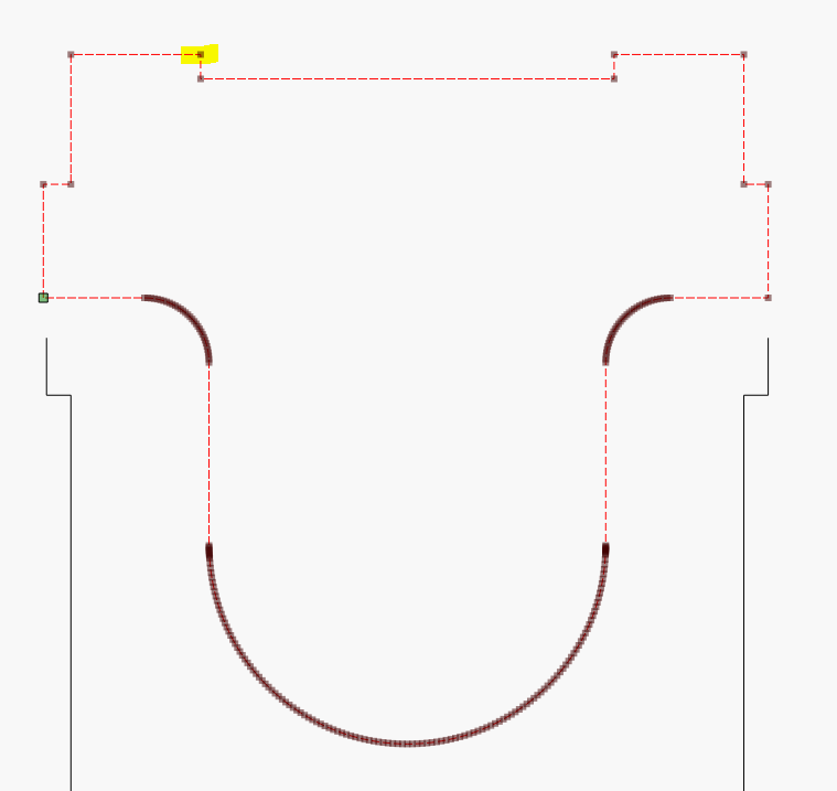
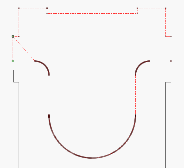
Now, my advanced issue comes when I hover over this node and hit B to break:
Now… I am hoping someone can explain that to me. Because I am at a serious loss to explain it. Worse, if I try to then break that new green node that popped up so I can drag the darn thing back where it belongs, it will not break… and dragging that node drags the whole corner. Now I can fix this by deleting that and rebuilding that whole section since I know the measurements… but this has happened to me a few times on this project and I need to understand why!
Green nodes are start/end nodes. Two per line segment or one per closed path.
Red nodes are selected nodes.
Gray nodes are intermediate nodes.
Conceptually simple, maybe, but literally complex. You seem to have an excess of nodes at the inner and outer rounded corners. I assume this was imported from DXF or once existed as a DXF. I suggest you go through Edit->Optimize Selected Shapes and see if you can get to a reasonable approximation. You’ll have a better time.
Hard to say exact cause. I’m speculating but a few possibilities:
This didn’t start as a closed path. It was 2 green nodes physically aligned but not joined. I wouldn’t still explain the end node to move but there may be other things going on.
Is it possible you have some garbage overlapping line segments scattered around in the file? That can cause unpredictable behaviors.
There are cases where joined line segments somehow get out of order and the green end node ends up in the middle of series of joined line segments. That can cause odd scenarios.
I’d suggest trying to simplify the object, then ensuring that it’s a properly joined closed path, that there are no extraneous line segments, and try again.
It looks like I might have a simple solution, but I will go ahead and post a lightburn file for this when I get in to work. This was converted from DXF.
I am not a graphics person… and when we started this business my designer taught me that to get files from our development stack to RDWorks (we used RDWorks at the time) I had to “save as” from inkscape (svg) to DXF R14 type and then import in to RDWorks.
After starting to use lightburn I tried to load the svg files directly, but doing that resulted in the object size being way off for some reason. It was killing our products. So I went back to exporting to DXF first and then importing, which fixed that issue.
I will also try your simplify trick and report back.
In addition to @RalphU’s suggestion, you should upgrade to the latest version of Inkscape or at least version .92. They changed the default DPI from 90 DPI to 96 DPI in that version.
If you are already using Inkscape, with these changes you’ll be able to directly load Inkscape SVG files into LightBurn and you’ll have a much better time for it. SVG and LightBurn both use bezier curves and designs in Inkscape will translate directly to LightBurn. You won’t be dealing with all the tiny line segments you’re getting going through DXF.