BINGO!!!
Watch this:
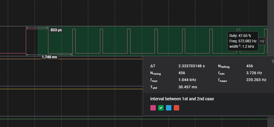
Saleae helped a lot ![]()
Tests had been done with wave analyzer connected to the cables near the LPS signal input.
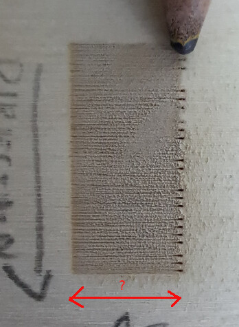
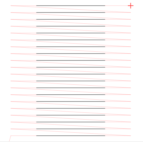
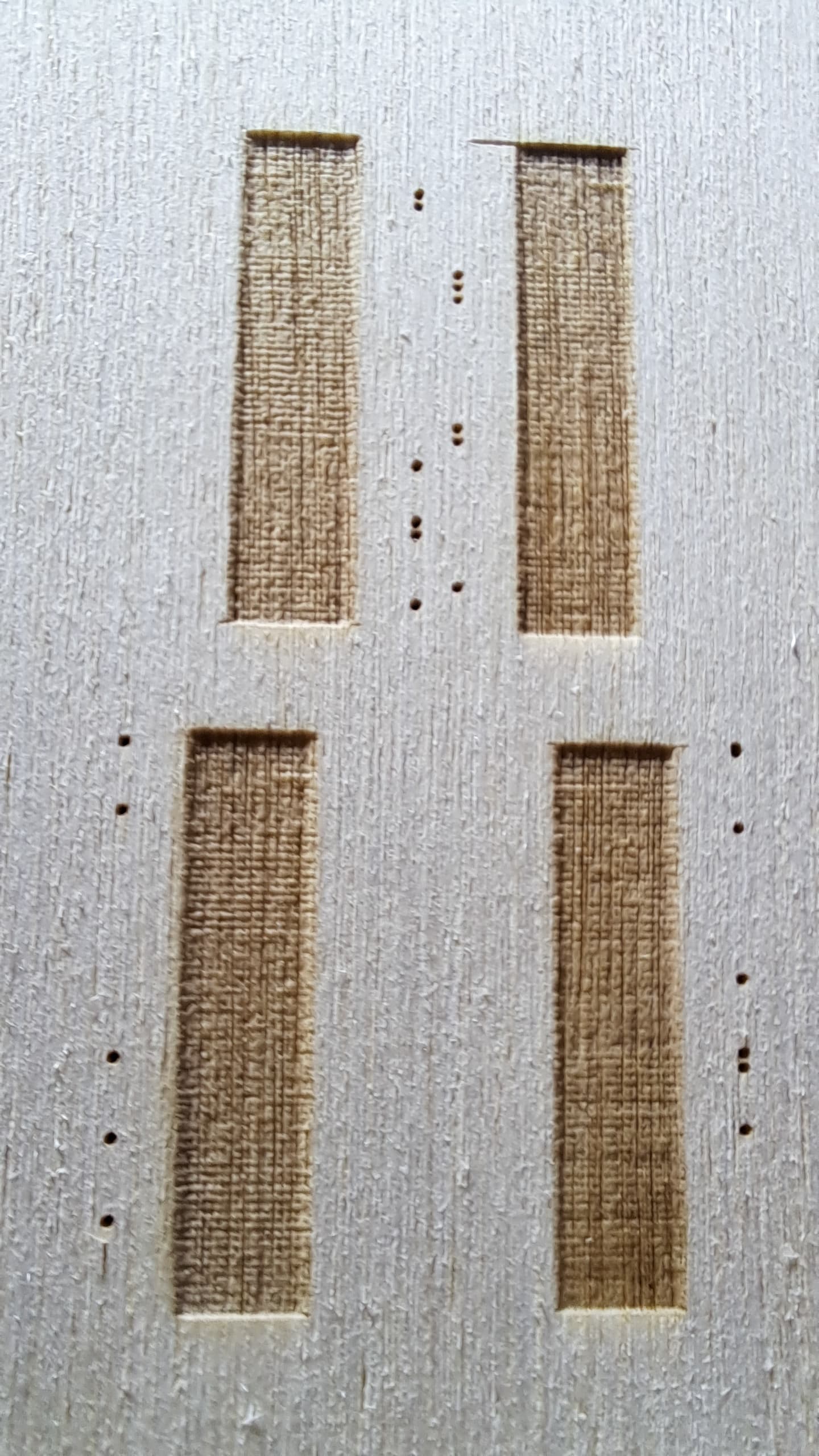
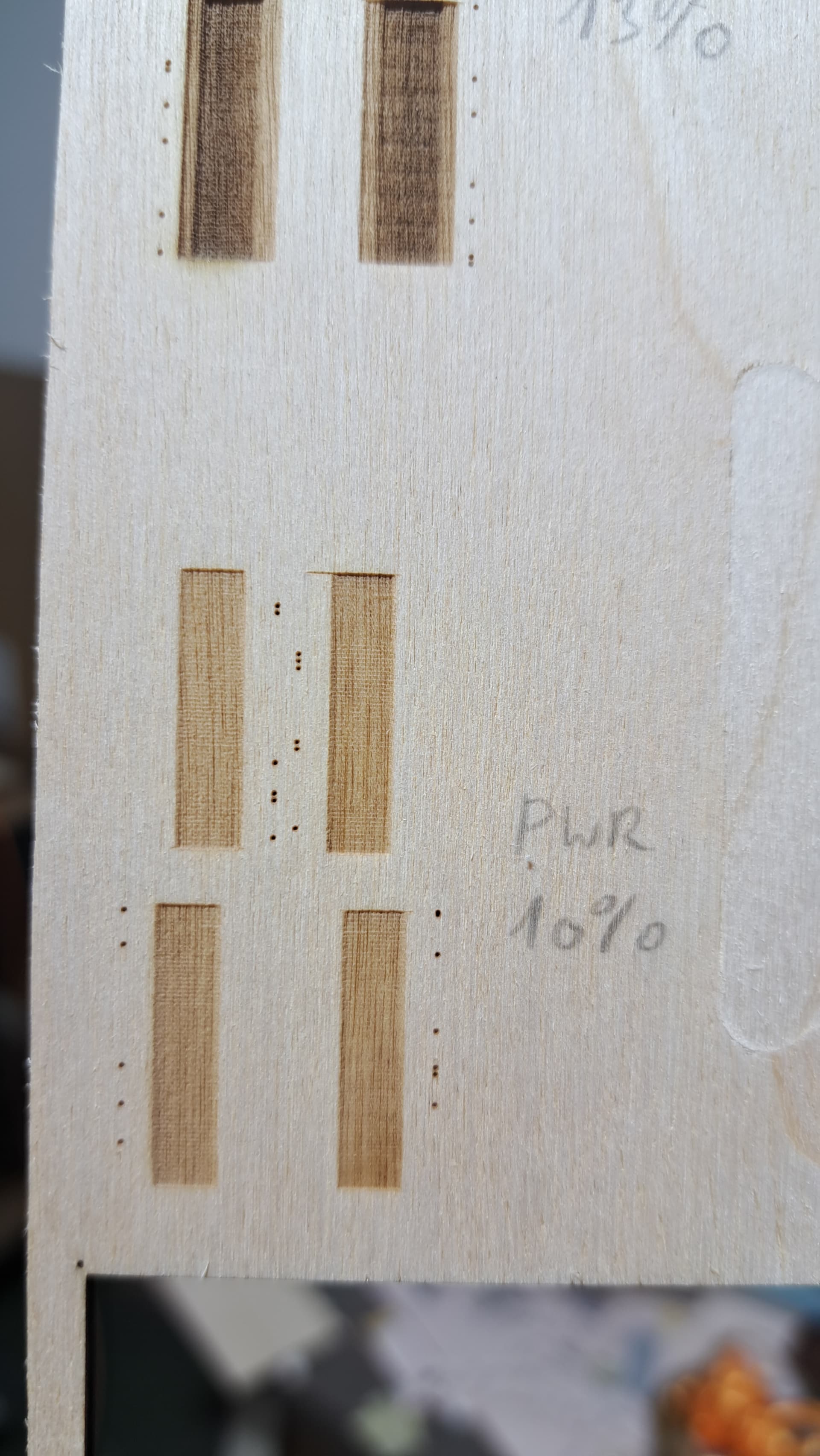
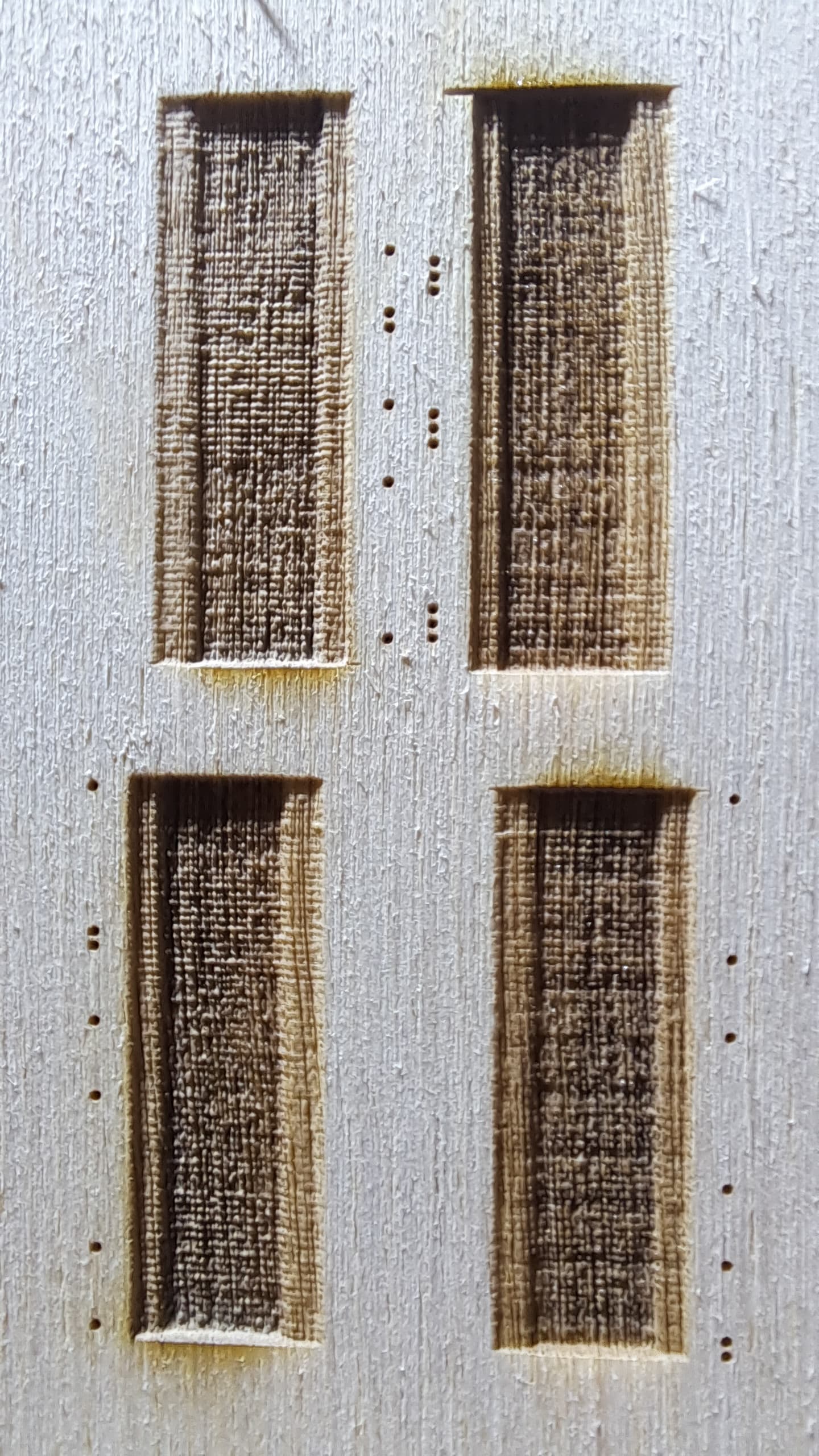
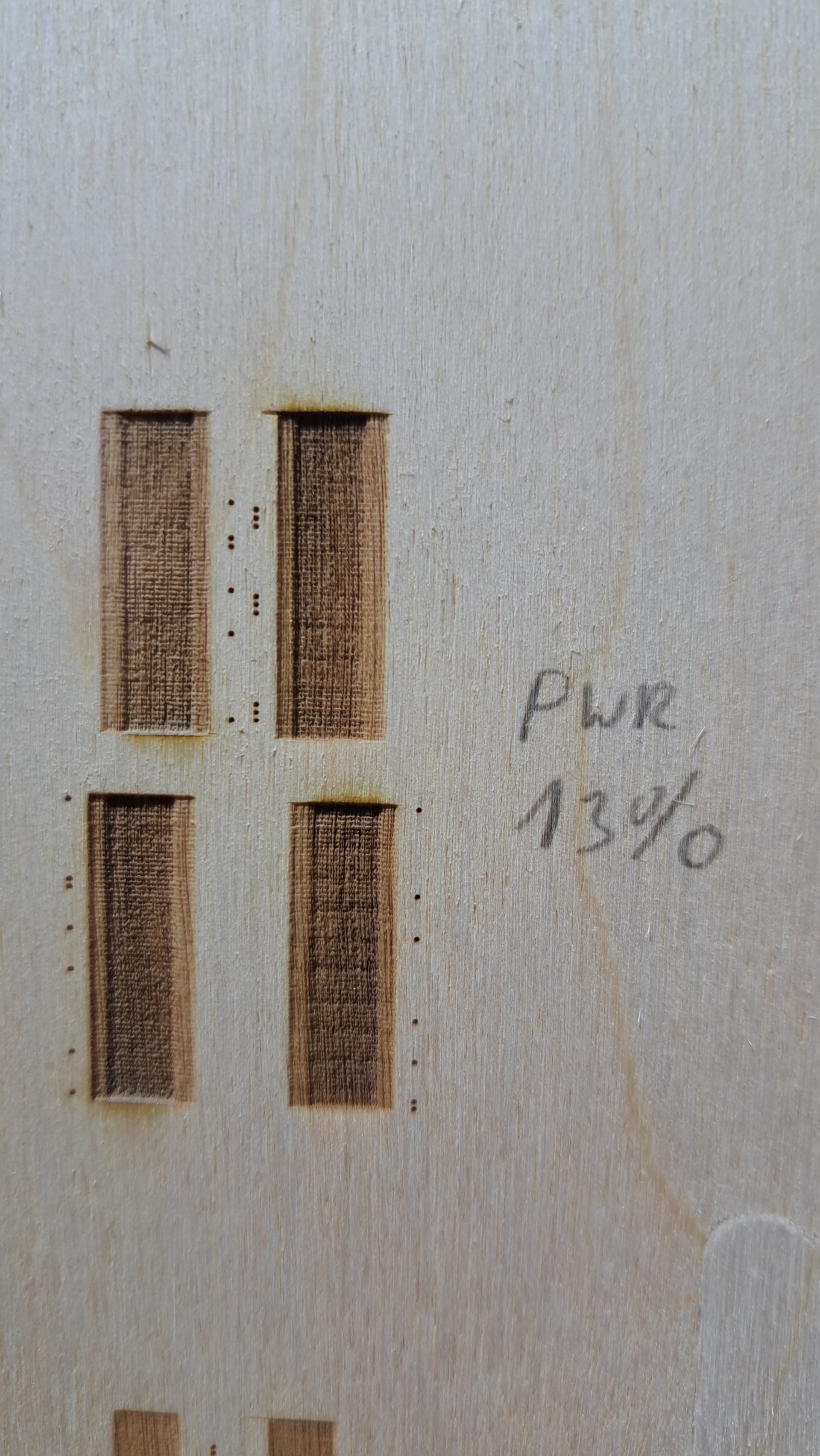
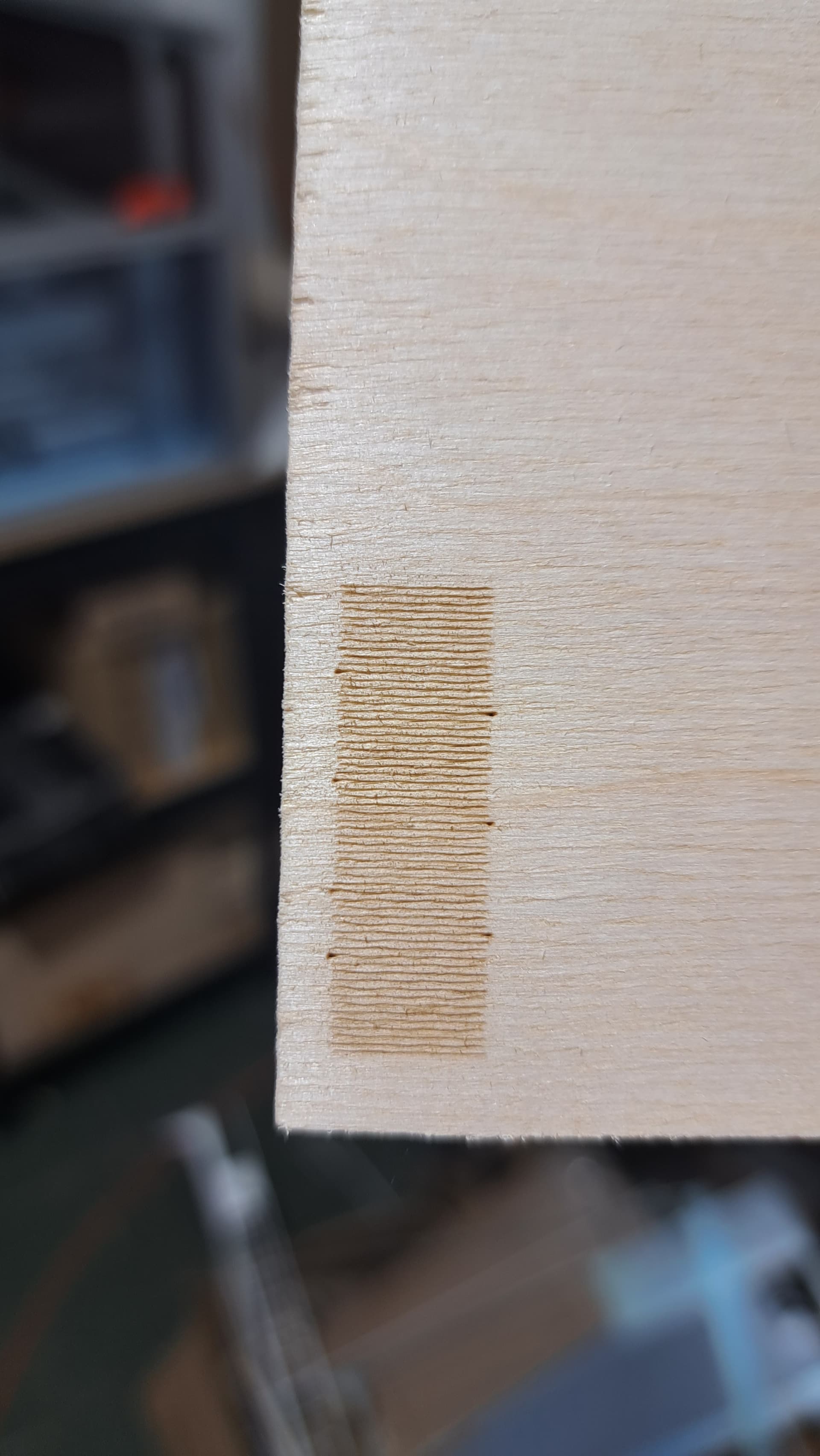
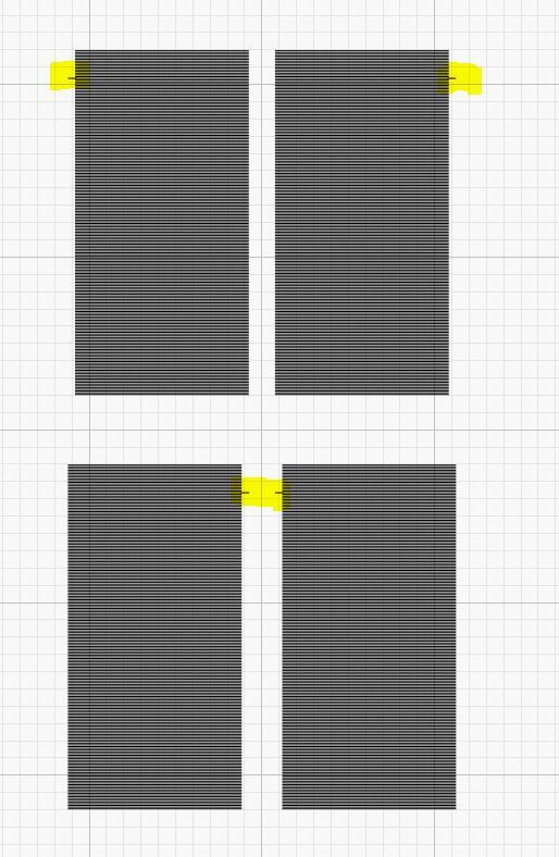
As I mentioned before, there is regularity…
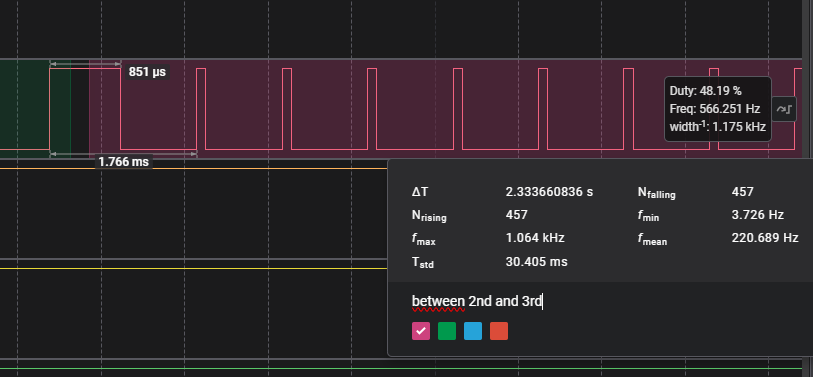
interval of 2,33s between 2 faults
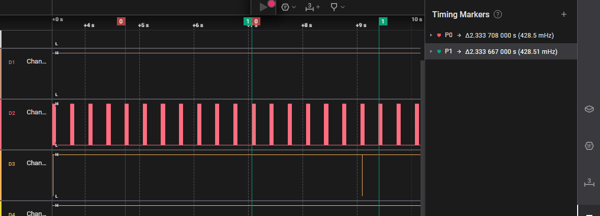
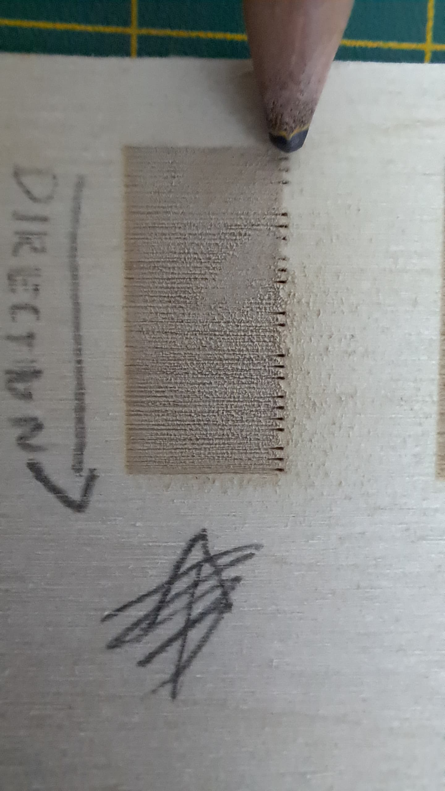
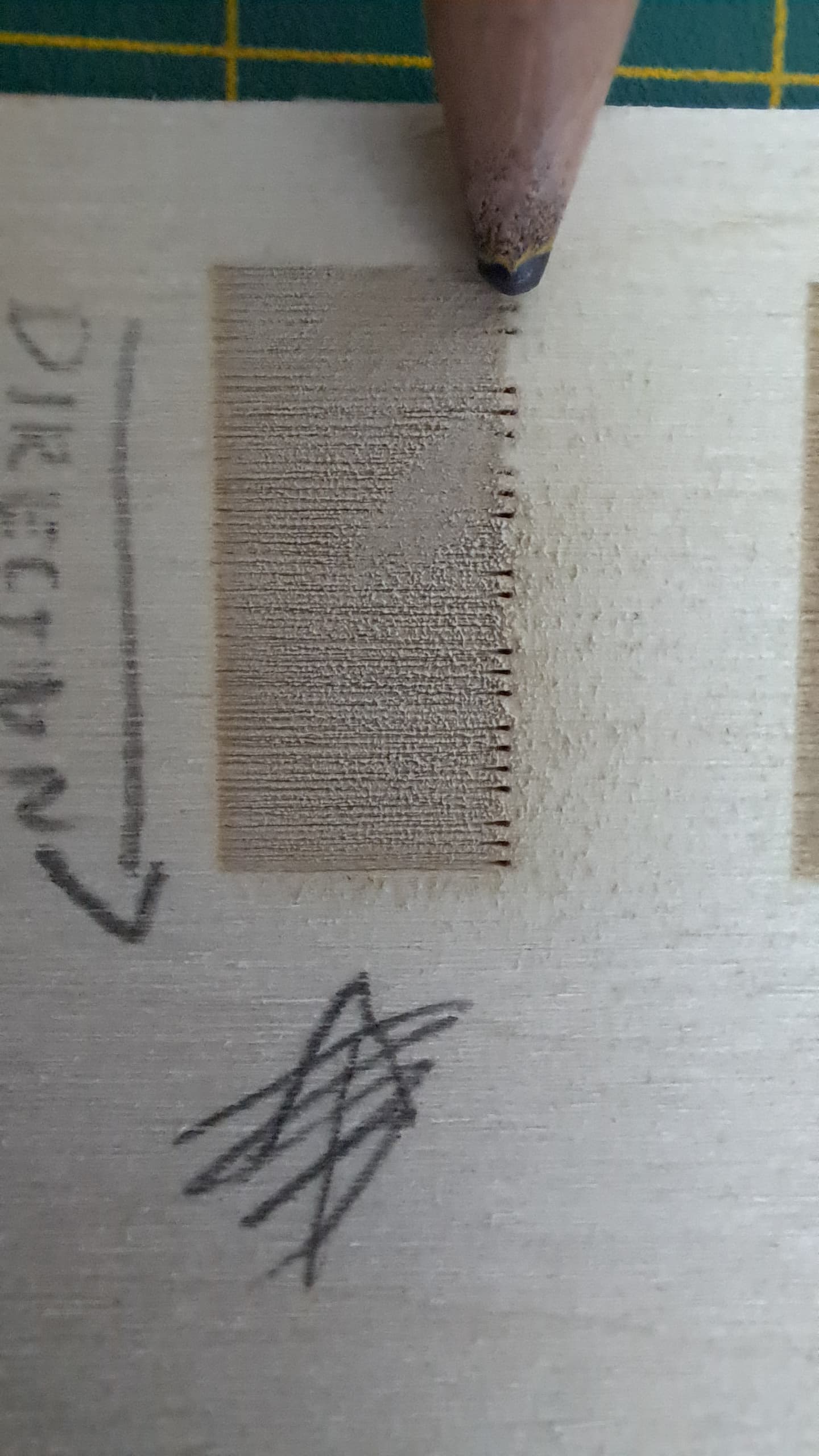
Here is representation of this fault on engraving:
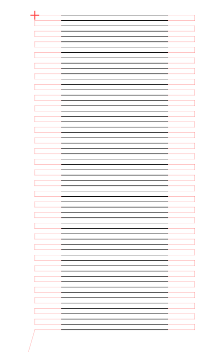
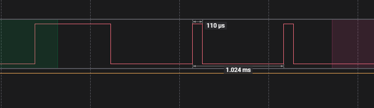
Can’t send whole Logic 2 file…
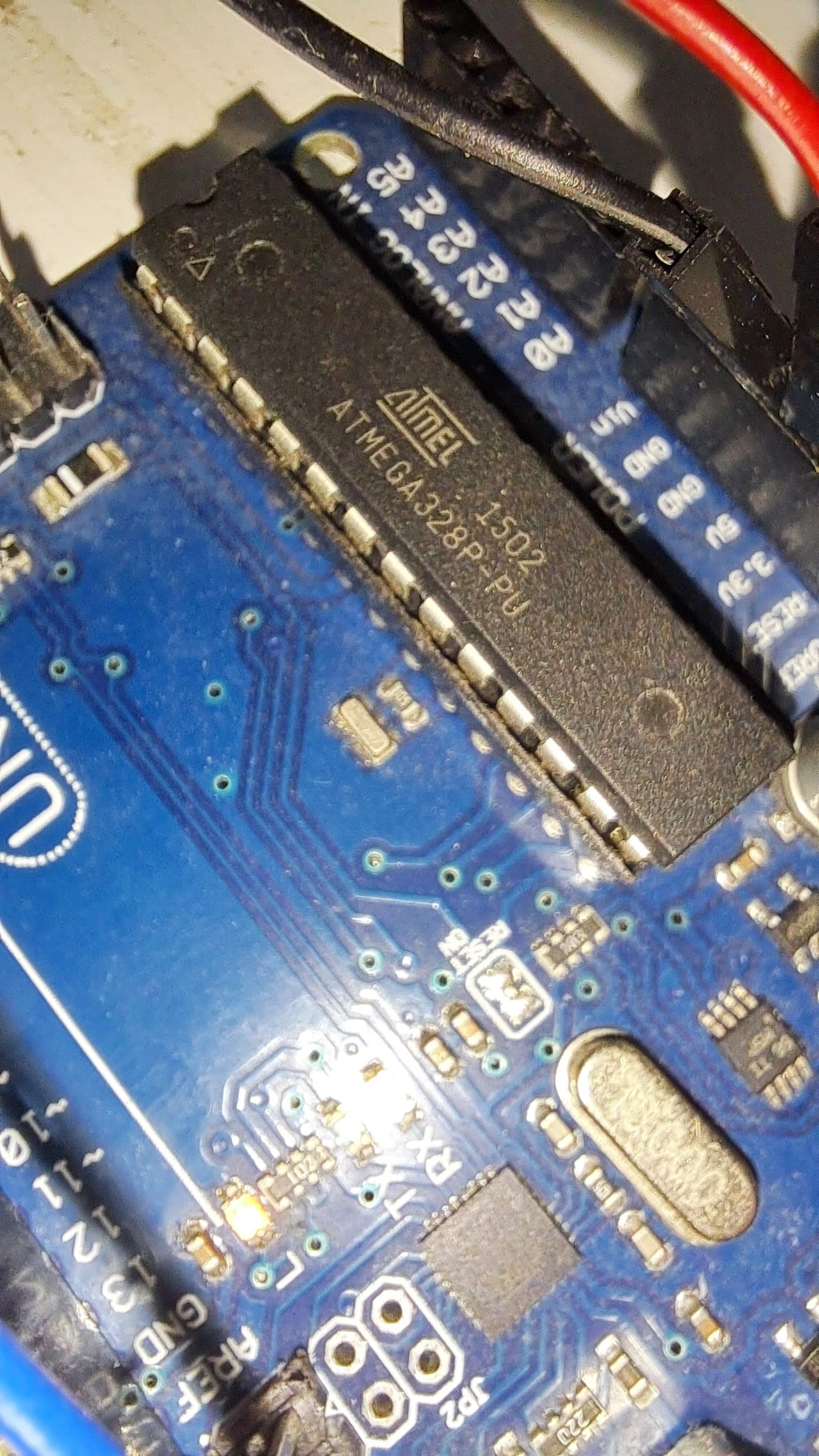
Glad, that it is a firmware fault, not hardware issue.
What should I do?
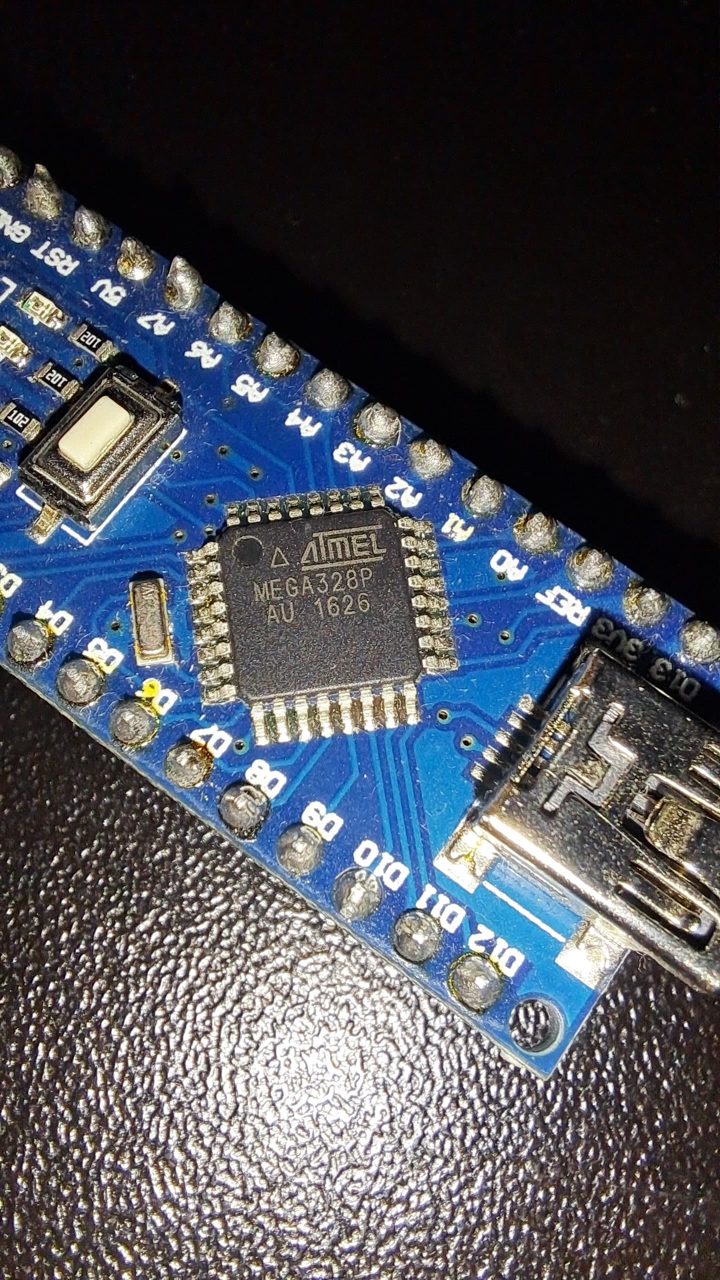
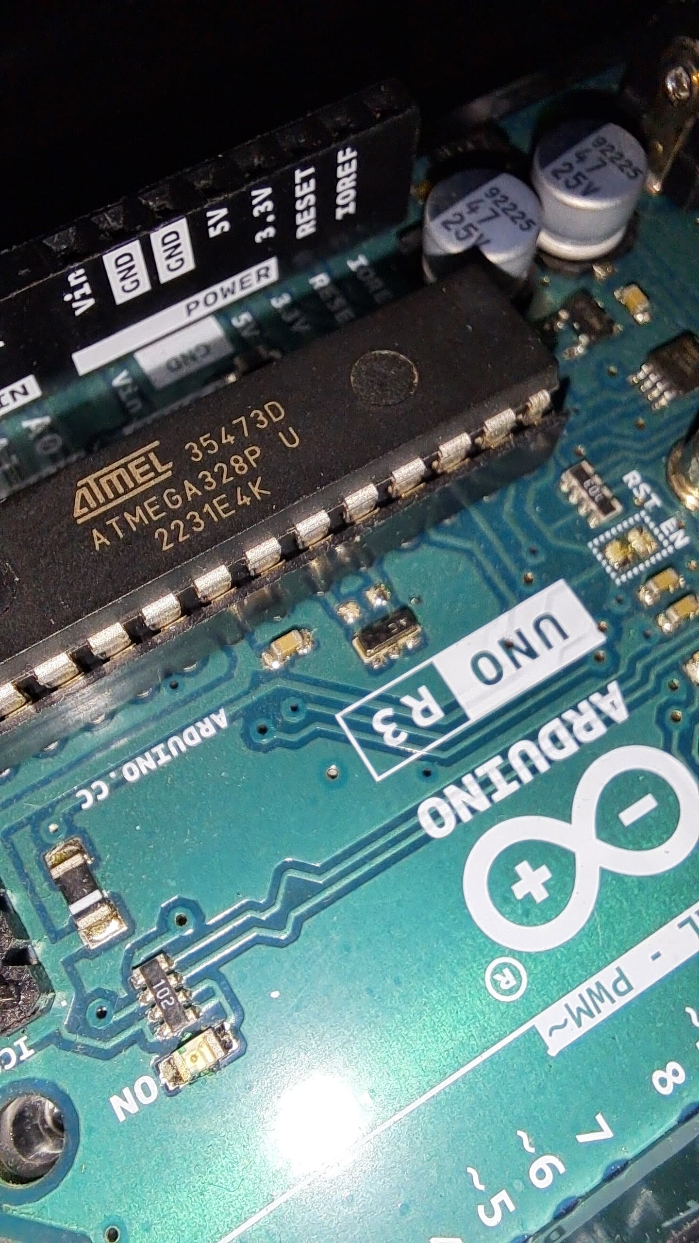
I’ve tested different comupters, all on Win 10, USB 3.0, 2.0, Arduino UNO R3, ARDUINO UNO clone, added super-duper extra signal USB cable from computer to Arduino. Should I test other operating system like Win7?
PS. I also tested the Arduino only, without connection to any laser hardware, and the result is similar - there are these brakes of wavelength so it can be Arduino problem (rather not, tested on 2 separate), GRBL problem (I’ll try to reboot and upload GRBL once again), or Win10 problem. It is said, that Win10 is worse operating system than Win7 and GRBL was constructed to cooperate with Win7. Maybe i have fault USB drivers?