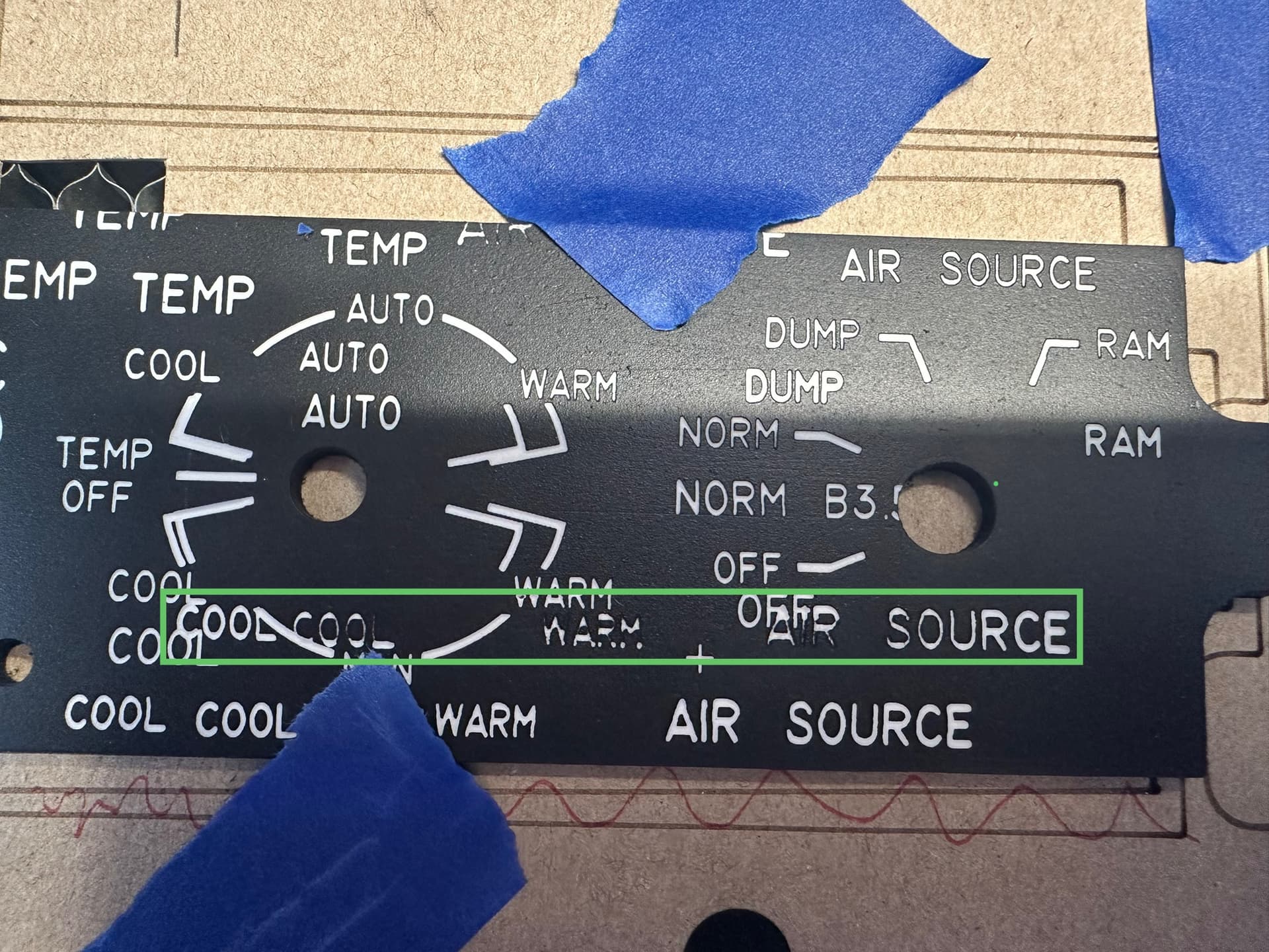
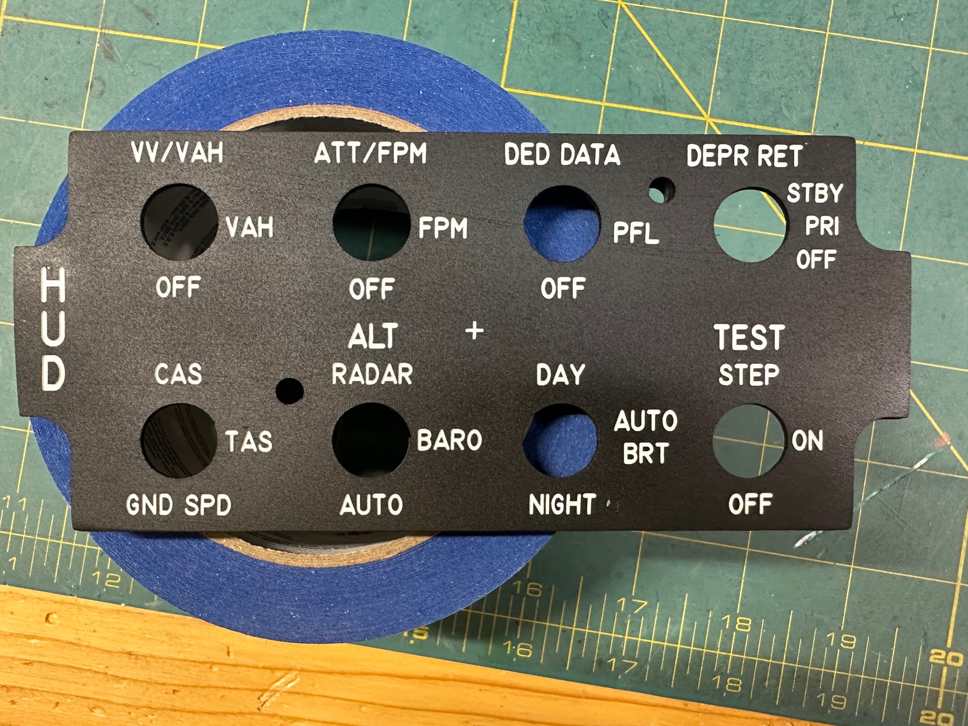
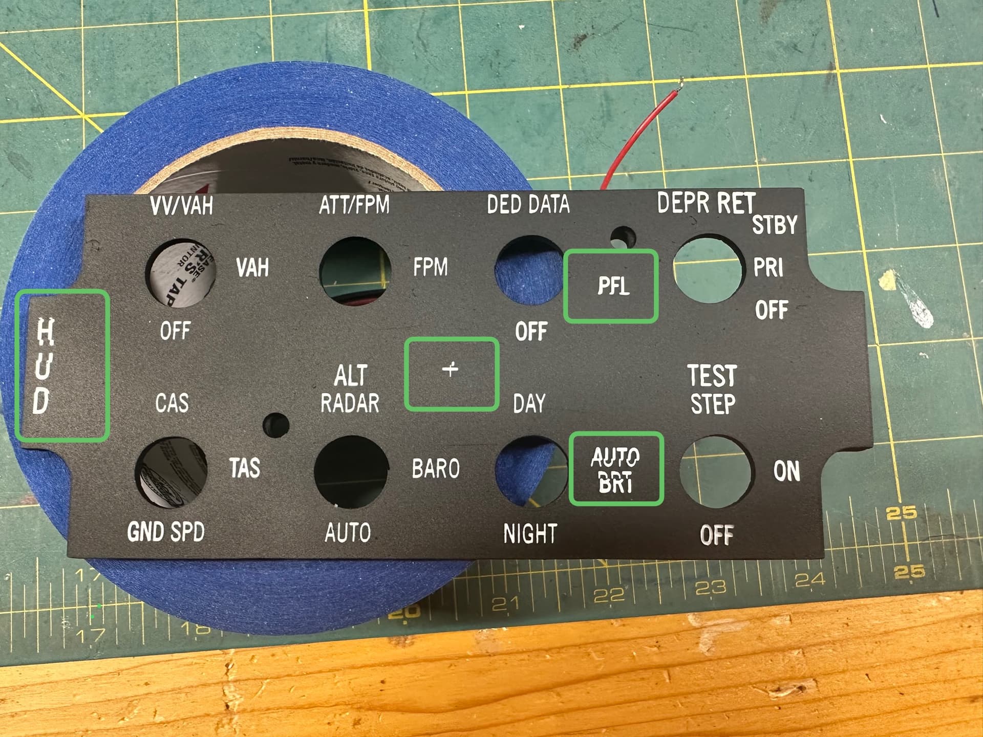
Take a look at the text in the green box. The actual string that was engraved was “ COOL COOL WARM AIR SOURCE” . Sorry about the other text but I was running out of room to test this. As you can see it is nicely engrave at the first COOL and the ends of SOURCE, but fades in the middle. Monport K40 CO2 laser engraving a 3mm sheet of white (painted back 2 layers) acrylic at 900mm/sec and 26% power (via the software) 1 pass, 1% overscan, bi-directional OFF, Crosshatch OFF. Alignment is good, belt tensions also good. No head unit play.
Why would it weaken in the middle? Thx
The response time for laser power supplies is somewhere around over 1 ms, which may be the 10% to 90% rise and fall time. The specs are very vague and perhaps aspirational for actual hardware.
A laser head moving at 900 mm/s travels across a 1 mm vertical bar in 1.1 ms, so the laser tube will not reach full power before it must shut down again. If the maximum power is 26%, the tube will lase at a very low power for most of that millisecond.
The tube’s response time depends on its temperature, the state of the gas due to lasing in the previous few milliseconds, and probably the phase of the moon. Because those thin features require beyond edge-of-the-spec response times, the results will vary across the length = duration of a single scan line.
You must reduce the scanning speed to something around 200 mm/s so the tube has time to accurately / dependably reach the programmed power level for very thin features.
Reducing the power by a corresponding factor of five-ish may not be possible, as CO₂ glass-tube lasers tend to not fire reliably below about 10%, again depending on temperature &c, and operating at the low edge-of-spec will produce marginal results.
Which means you may need three coats of paint or a different paint or something along those lines to match up with the laser’s actual performance.
I believe @ednisley is correct. I usually use the placard specs on the lps as <=1mS for a response time. It’s difficult to measure.
If we use the worst case of 1mS running at 1000mm/s (makes the math easier) then the head is moving 1mm during that 1 mS.
The best resolution you could possibly expect is to toggle the tube on/off every mm, meaning at 1000mm/s your best resolution would be 24.5dpi, 500mm/s would be 50.8dpi and 250mm/s relates to 101.6dpi.
It’s easy for most of these machines to outrun the lps. My machine can run 1650mm/s, but my engravings are generally around the 200mm/s mark.
This is exactly what @ednisley states, just put in a slightly different way.
It’s likely costing you time to run that fast. Use preview to get an estimate of how long the job will run.
Here are two identical sized rectangles. One is a normal view, the a bit wider to show the effect. One running at 1000mm/s the other 500mm/s. Note the slower speed is almost twice as fast, job wise.
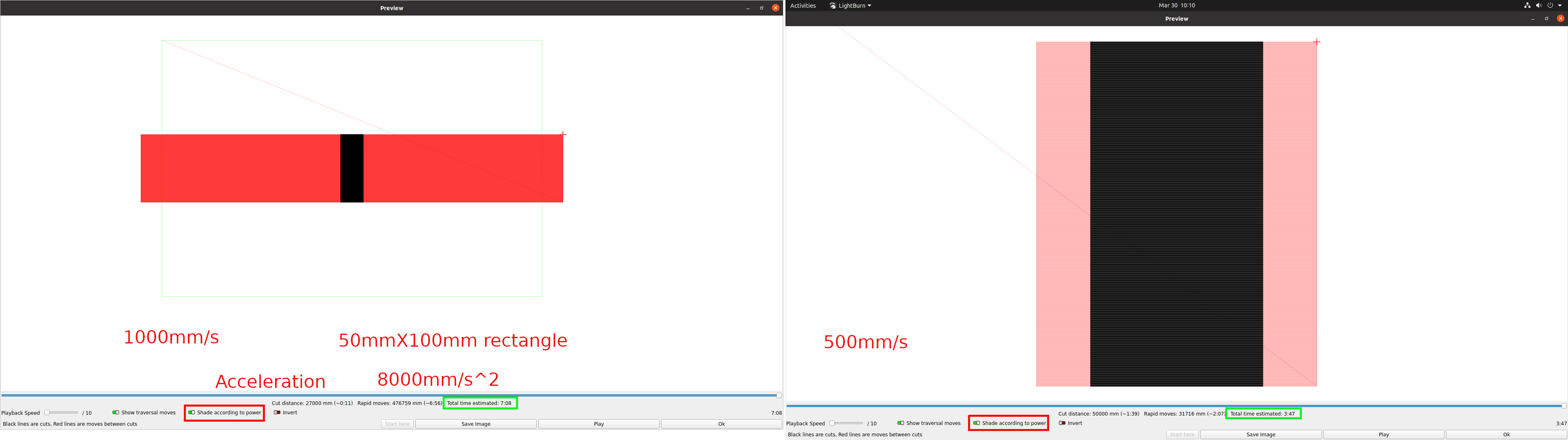
Green rectangle, on the left image, is actually the defined work area. Since it’s outside the defined area of the Ruida, it’s more than likely it will generate a slop error of some type.
Have fun

Thank you both for the explanation. I am not actually running that fast just to save time though. I am not doing this commercially so I really don’t care how long it takes to do each panel - just want it to look OK. Unfortunately I only use this very infrequently and have to refamiliarize myself with all the procedures and settings each time. But I have done panels that are the same width (≈6”) with the text spaced apart as in this example I showed - that came out ok! Something happened to some setting that i can’t figure out. Bi directional used to be fine, but now it ghosts horizontally so I have to turn it off. And you’re right about the power - if I go down to 22% or lower it is not very good at all, even at slower speeds. I have done resolution test at different speed/power settings and 900/26 seemed to be the best. Even slowing down to just 800 I could see a difference.
I just wonder what could have changed that now makes it do this.
Are you saying that LightBurn treats that whole line of text as “one” item? It would seem to me that the image would be the exact opposite of what it is doing then - the beginning weak - while the laser ‘ramps up’ - then strong and stable in the middle of the traverse while the laser is up to power - and then the text gets lighter and weaker at the end as the laser power ‘ramps down’?
How big are those letters?
I doubt you can get to 900mm/s within the short stroke of the letters.
While you’re in there, what acceleration value do you have for the X and Y axes?
The text is 3.5mm tall. I’m not sure where to find the acceleration values.
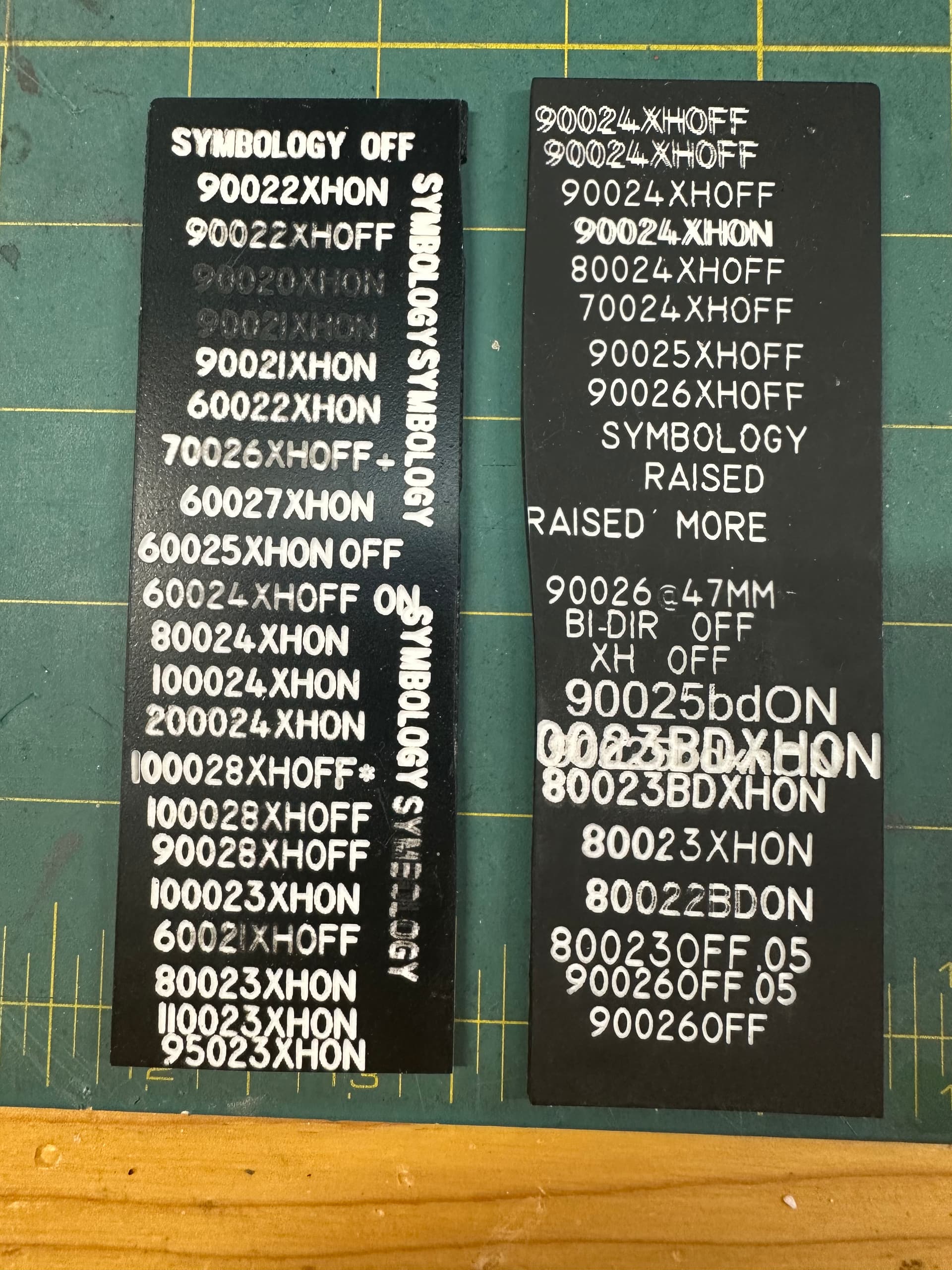
Here is a pic of the earlier speed/power/bi-D and crosshatch on or off tests. You can see that very bottom 900/26 looked best to me. Also, that one just above it - the 80022BDON seems to have this ‘weaker middle’ section a bit as well?
And also a pic of a panel I did awhile back. And it came out ok. Same width and approximate spacing as in the panel with the green error box…
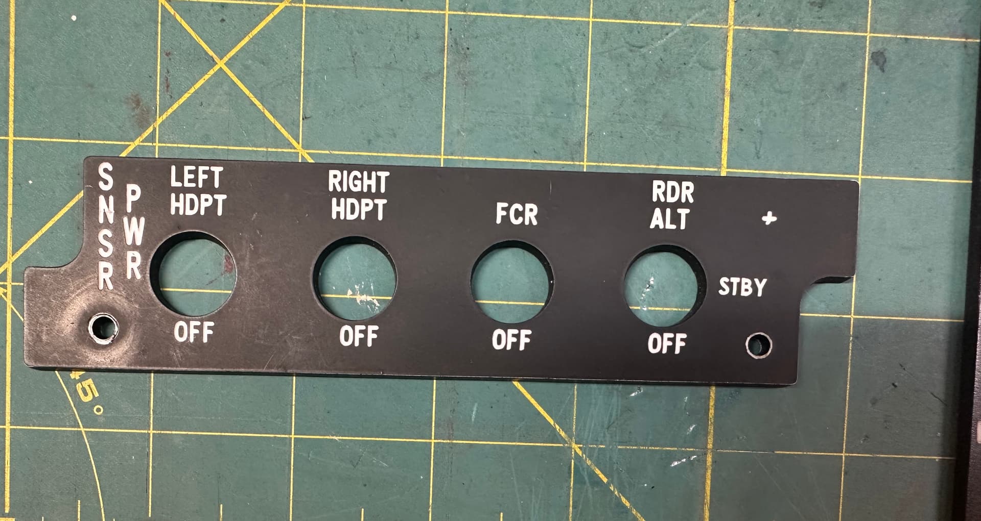
I am able to get very good clean results at 900/26 (BD and XH off) as it is right now if I only do a single “word” or line segment at a time, but as I discovered a bit too late for this AIR COND panel, it apparently ‘creeps’ to the right a slight amount each time - I didn’t realize it until I saw the circular lines no longer aligned to the circle cutout at the left. Every new engraving moved a bit to the right of where it should have been. I then tried homing after each engraving and it didn’t seem to drift then. That may be what I’m stuck with but I sure would like to be able to do one whole panel at a time like I did with that SENSOR PWR panel. Just don’t know what the heck changed…
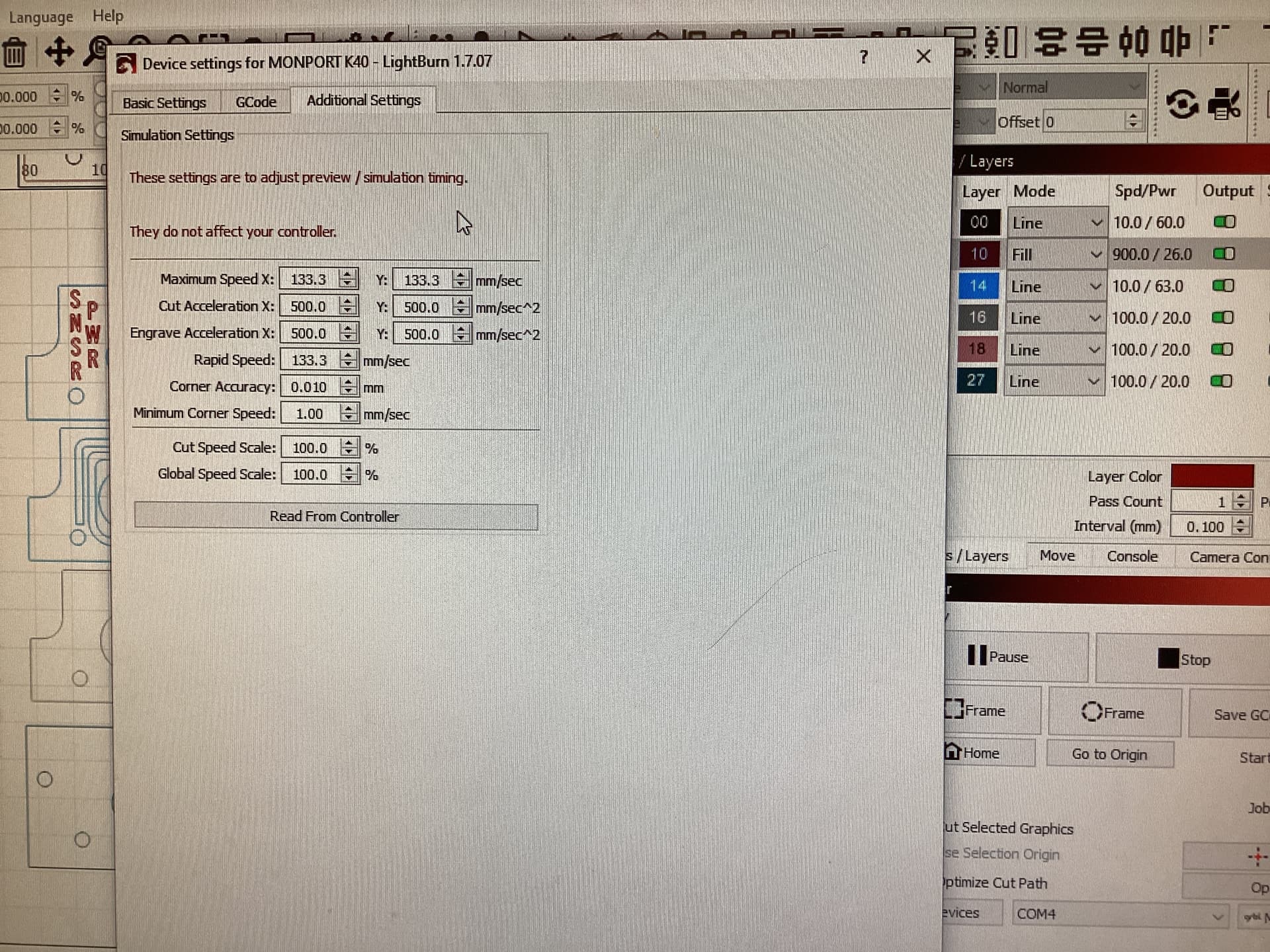
They would probably work, did you click on read from controller? Sometimes it doesn’t get updated.
Grbl has a numeric system for it’s settings. This is old, doesn’t have $32, but most of the others are fine. Remove the .txt extension.
GRBL_Settings_Pocket_Guide_Rev_B .pdf.txt (214.4 KB)
This is from the pdf.

These seem relatively slow as printed. There is an acceleration calculator available.
I’m still confused if you’re using mm/s or mm/m.
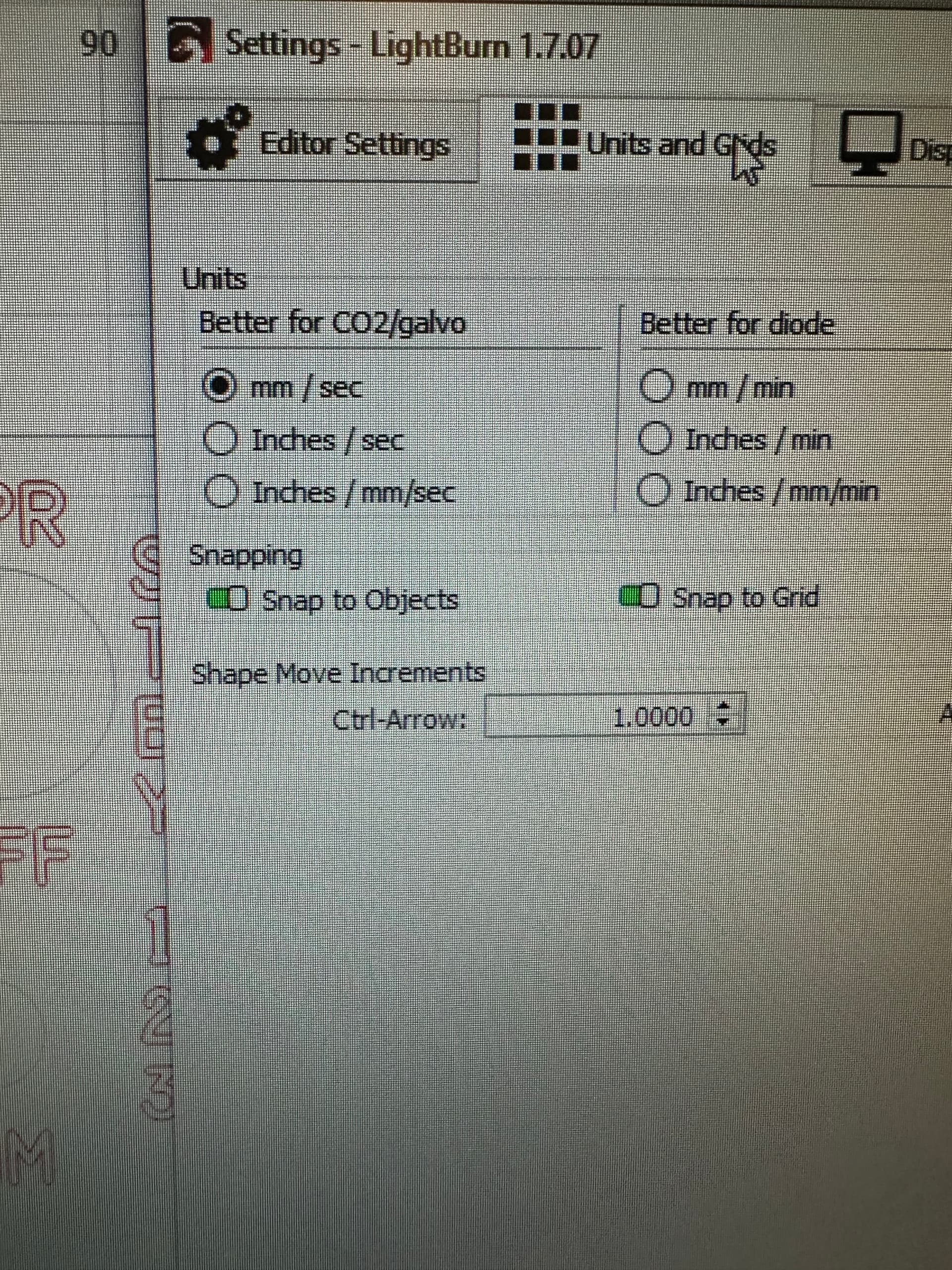
Check what values you have for

These are your maximum speeds.
According to your information, the machine has an acceleration value of 500mm/s^2, it also implies that 500mm/s is maximum speed.
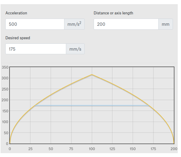
To reach 175mm/s it would take that machine about 30mm.
900mm/s is pretty fast, I doubt if these numbers are right, you would ever make it to that speed.
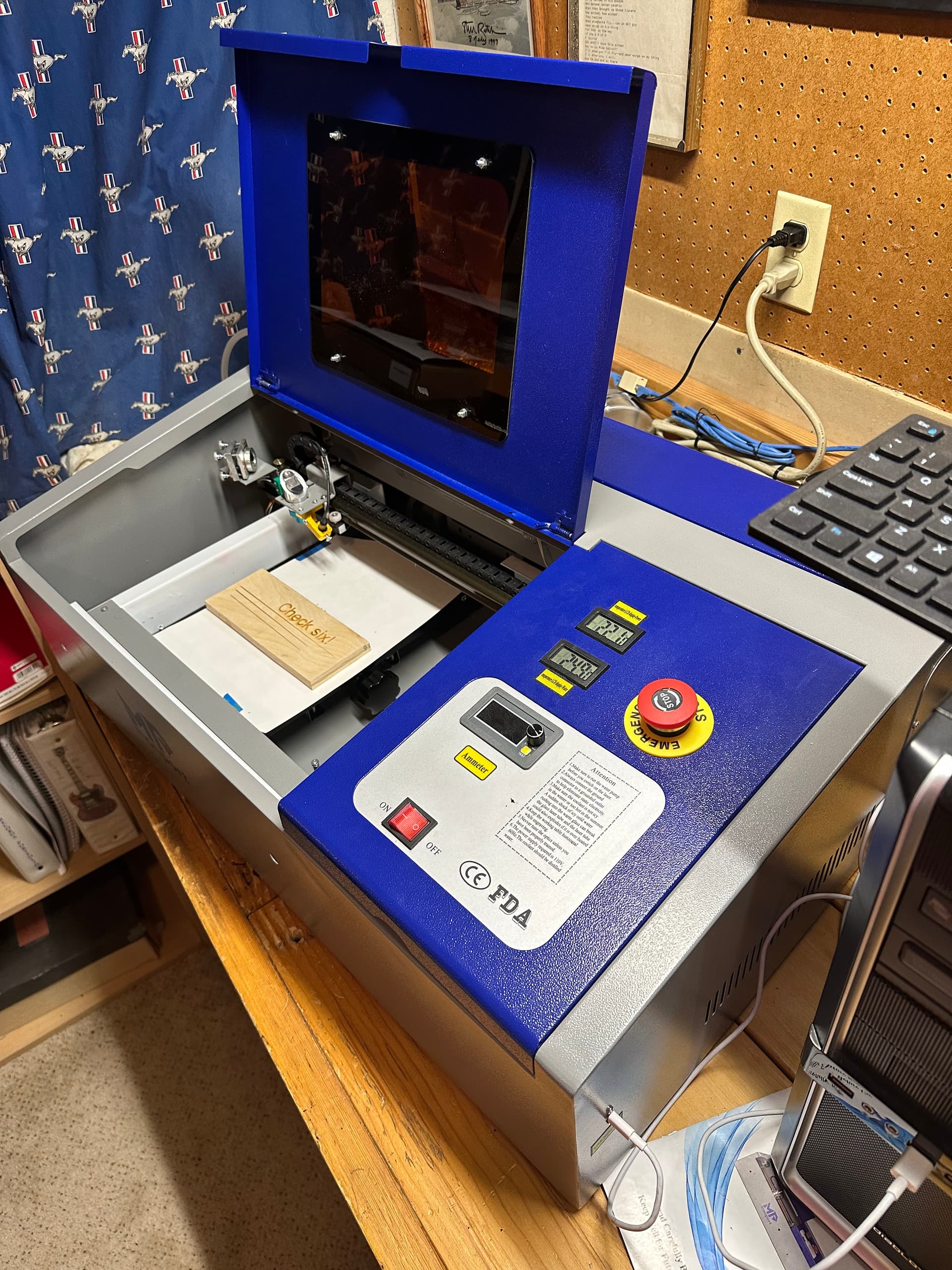
Any chance we can see a photo of your machine… we all love a diy anyway.
The cure for that is generally measuring the offset and filling in the Scanning Offset Adjustment table for all the speeds.
To a large extent, there’s no way to know what the machine used to be doing that it is doing differently now. The best we can do is observe the current symptoms and diagnose the possible causes, without wondering what came before.
Power supplies age, tubes age, and machinery ages: there’s no setting for “Produce good results” that you’ve inadvertently turned off. 
Link to the manual
Yep a “Produce good results” button should be mandatory on these. But I really appreciate all your help everyone is providing.
I was actually able to make this panel last night, but I literally had to do one word section at a time, and re-HOME and frame before each new one. Took a long time. This was at 750 and 26% and 1% overscan, x1 pass, and crosshatch and bi-directional OFF. If I try to just do the whole panel at once (which I was able to before it lost it’s mind) then I get various errors, like you saw in the original post in the green box…
This is a K40 type and they are generally maxed out at about 300mm/s. Even the manual you posted advised a maximum engraving rate of about 350mm/s.
I really doubt it can even reach the specified speeds.
The offset in the last posted photo appear like a grub screw working it’s way out on the motor pulley, on the X axes.
The manual and the simulation values show the laser tops out at 133 mm/s on both X and Y. You can set any layer speed you want, but the controller will not run the steppers at more than the maximum speed set in the Machine Settings.
IIRC, GRBL uses mm/min for the speeds shown in the Machine Settings, so you must convert from mm/s when comparing the numeric values.
The 500 mm/s² acceleration means it requires about 18 mm to reach 133 mm/s, which is likely much longer than 1% of the speed will produce, particularly for one-word-at-a-time scanning.
The result is it’s proceeding at a much slower pace than you think. That makes diagnosing the problems much harder, because all our assumptions are wrong.
Those are likely due to USB communication errors dropping out chunks of the commands. Using a better cable, typically one with molded-in ferrite cores, seems to improve the results. The Troubleshooting page has some suggestions:
An earlier discussion suggests how long it takes to recover from various other non-solutions:
Wow that’s a lot of info. So are you saying that since my machine is set at 133 mm/s, that ANY number I select above that is disregarded, and the laser engraves at that max setting of 133?
Also, the manual really only shows recommended CUTTING numbers, no engraving numbers. So I had to guess all these numbers from the get go. Including the overscan. I did not know the math behind it. Right now I believe the 1% came out to 4.5mm so I’ll have to increase it to >18mm ?