Struggling to power FBLI-B-LV4 galvo controller (need 5V input)
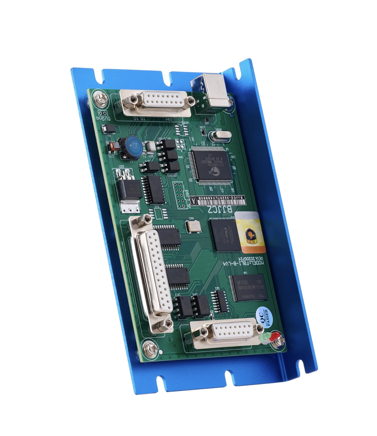
I recently built a fiber galvo setup from “scratch”. Hardware is all in place (Raycus 30W source, Cloudray RC1001-V1 scan head + PSU, lenses, frame, etc.), but I can’t get the controller board (FBLI-B-LV4) to power on.
The USB-B port only handles communication to the PC (EZcad), not power.
Vendor told me the board needs 5V fed in through the DB15 “power/IO” connector.
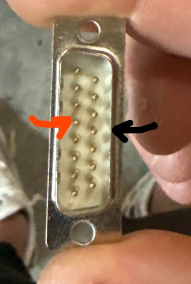
I tried splicing a USB cable (red → pin 4, black → pin 12 per the pinout) but no luck. Board still won’t light up.
I’m considering wiring a dedicated 5V wall charger into the DB15, but before I start cutting more wires, I wanted to see if anyone here has done this.
What’s the proper way to supply the 5V to this controller? Do people normally wire in a separate 5V PSU, or is there a standard adapter cable for the DB15?
Any insight or other information would be greatly appreciated!
Mine has a separate 5v supply, pretty good sized. Agree with Jack on amperage, wouldn’t hurt to go more. Power it on/off however you like. I have cracked mine open a few times but didn’t make note of the amperage.
I open stuff up, then realize after I put it back together I should have taken a photo. It’s so cheap and easy to do it with your phone compared to when I was a kid it had to be processed.
Next time you’re visiting, take some photos so we can compare… I’ll open mine up some day.
I’ve managed to get power into the board by wiring 5 V and GND directly into the through-holes. The board lights up fine, and EZCAD2 now recognizes the device, I even got the driver updated.
Here’s the issue: when I try to run the galvo, the laser doesn’t fire. Instead, the red LED on the board flashes only at the moment it should be lasing (not just constantly on). That makes me think the fire signal is reaching the board, but something downstream isn’t letting it actually emit. I assume that’s what the red LED is doing.
I’ve already ordered a dedicated 5 V PSU, but honestly, if the PC’s USB 5 V was just weak, I’d expect to see some firing, even if inconsistent, rather than nothing at all.
I may need to check the pinout of the DB25, but I find it hard to believe it’s wrong. Really starting to drive me mad!
I’m impressed you built one from scratch. I considered it but the BOM was more then buying a new one if I wanted a JPT MOPA source.
Is it possible that you need to power both 5V in pins? Something I intend to check next time I open it up.
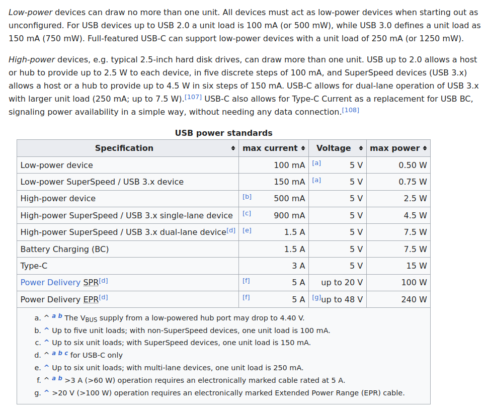
I would agree, I wouldn’t depend on a 5V supply restricted to 1.5A for a 3A feed.
If you can’t supply it with enough current to operate, it’s not going to be 5V anymore. I don’t know of any computers that will operate at all when you can’t provide them with operating current.
So, no, at 150mA or 1/20th of the required current, I wouldn’t even expect an LED to illuminate.
At least you’re optimistic.
Most USB, especially 2.0 is restricted to pretty low power levels.
After thinking it over last night, I landed on the same idea. I’m planning to feed +5 V into pins 4 and 5, and tie the negatives from my 5 V / 3 A PSU into pins 11, 12, and 13. I am hoping this works. I appreciate you taking the time to help me.
Thanks, I noticed the same thing. Honestly, I couldn’t justify pulling the trigger until I found a laser source at a heavy discount. Ended up saving a good chunk overall.
Update for anyone who runs into the same headache:
I was able to get 5V into the board by tapping the 5V and GND pads (near the IO DB15). I tested a few ways of feeding the 5V, but the most reliable was through the DB15 connector:
+5V into pins 4 and 5
Ground into pins 11, 12, and 13
I also shorted pin 1 to ground just in case I needed to bypass a fault input (door, e-stop, etc.)
With that setup, I can get the laser to fire. That said, it’s still weak across all settings and not marking material yet, so there’s more debugging ahead.