Swapping Y Axis from gantry to rotary with a switch

Disabling the drive does turn off the holding torque to the motor. I am going to proceed with this solution because it is much simpler to implement (KISS principle). All I need is a SPDT switch.

After much trial and error, I have managed to get the rotary attachment functioning and calibrated. Using a SPDT switch the gantry or rotary drive can be selected. Toggling rotary enable in the software changes the parameters to the motor driver selected. Everything seems to be working as it should.

2 Likes

For the benefit of others, would be great if you are willing to share the details of your process and of final result. Pictures? :slight_smile:

1 Like

I would be glad to. I will try to take some pictures tomorrow or this weekend.

1 Like

Can you share how you wired it? That’s what I’ve been waiting to do with mine since I have hybrid steppers on my X and Y axis and a normal stepper on the rotary attachment. I’m going to need to install a dedicated driver just for the rotary attachment and just not sure how to wire it in without having to keep swapping out the drivers when I used it. Thanks! Jason

Jason, I am not sure of the difference between a hybrid stepper and a normal stepper. This is the drive I used for my rotary.

DQ-542MA

This is for a two-phase hybrid stepper. Would this drive work for your rotary motor?

1 Like

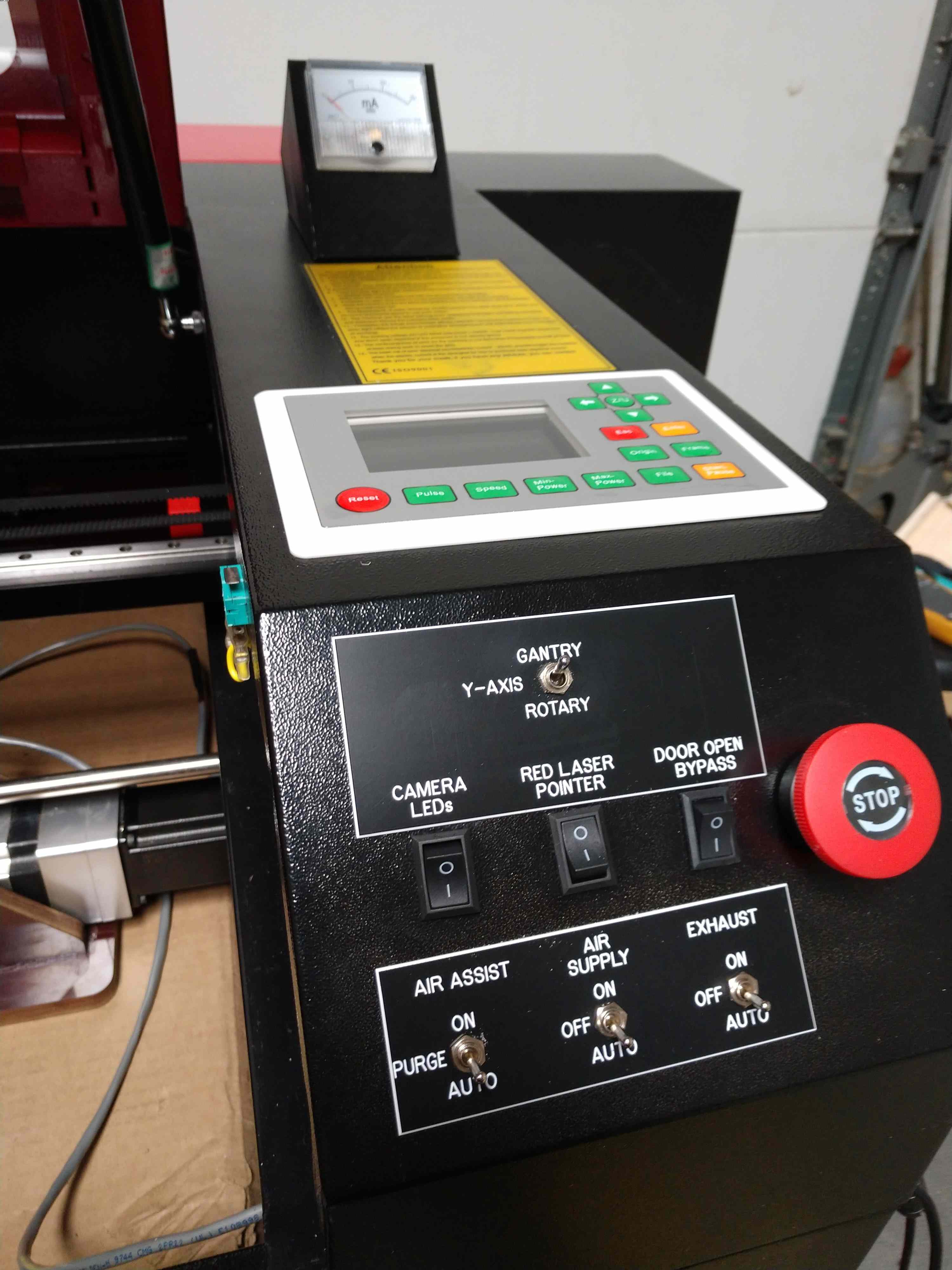
I added a switch to top of the front panel to select which driver to use for the Y-axis. Select Gantry or Rotary.

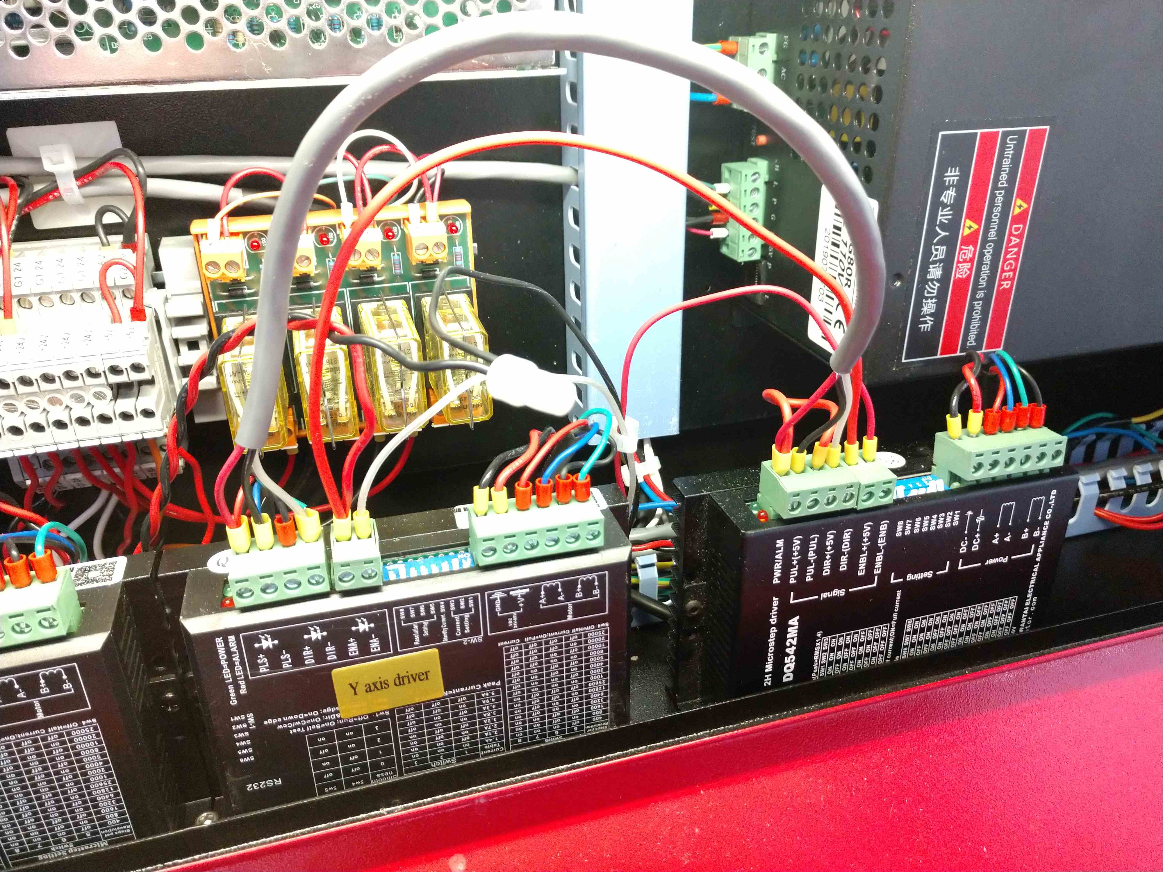
The three wires between the drives are from the switch. Black is 5V- (Com on the SPDT switch), Red from gantry selected (ENA-), White from rotary selected (ENA-). The ENA+ on both drives are connected to 5V+. The drive is enabled when the ENA input is an open circuit.

The step and direction are paralleled to both drives.

With this setup I can jog the gantry over the rotary attachment where it needs to be. Select the rotary drive with the switch. Select rotary enable in the LB software and burn the job. When finished, disable rotary in the software and switch back to gantry on the front panel. Everything is back to normal.

5 Likes

Nicely done! :slight_smile:

Hey Stan, sorry for the late reply. Here’s my stepper drivers. The blue drivers are the hybrids, they have a feedback port to get feedback from the motor. I just realized these are 3 phase and so are the motors, but my rotary attachments are 2 phase, that’s the other reason why I bought a separate stepper driver.

1 Like

Stan, what are the 4 relays for directly behind the Y axis driver?

1 Like

You should be able to wire yours the same way did.

1 Like

I am using the relays to control the
exhaust blower and solenoids for the air supply and air assist.

Ok great! If I get some time tomorrow afternoon I’ll give it a go! Thanks for your help Stan!

Would you mind sharing some info on how you wired the relay to the blower? I hate going behind the machine to plug and unplug it, it’s too loud to leave it run while I’m loading files to the machine.

For your air assist are you using the kit from Cloudray laser?

Thanks again!
Jason

I will start another post tomorrow for the blower and air assist.

I am using compressed air and not the air pump that came with the laser. My setup is a little different than cloudray. It uses a pressure regulator and two solenoids with two flow control valves.

1 Like

Thanks Stan, really appreciate your help! Jason

Jason, Were you able to make any progress?

I have not been able to make any drawings for the blower and air assist controls yet.

Hi Stan, Unfortunately I didn’t get a chance to do it over the weekend. I’m hoping I’ll get it done this coming weekend. I’m currently installing the ultimate air assist system from Cloudray and also looking to see what I can do about controlling my noisy exhaust fan from a switch on the front panel like you have. When I finish the air assist I’ll start working on the rotary install. Well the truth is that I still need to instal the hybrid steppers and drivers as well although the rotary still in not currently connected. I may do a temp rotary set up (if I have to use it) until I get the time to swap in the new motors and drives.

Do you think this relay will work good for my exhaust fan? The fan is 110v. I see on your pictures the relays have some diodes. Will I need them also?

That is a 120VAC coil relay. For the output of the controller to operate the relay you will need a 24VDC coil. The contacts of the relay can be any voltage (AC or DC). The diode across the coil helps protect the output circuitry of the controller from back EMF when the relay is de-energized. It’s a good idea to include that. Automation direct offers a relay with the diode built in (QL2X1-D24). You can also add your own diode across the coil.

This topic was automatically closed 30 days after the last reply. New replies are no longer allowed.