so i have used lightburn since it came out on my k40s with c3ds. now i got my thunder nova35 in and this is my first machine with a ruida controller. i finally got it working with the dsp upgrade and tested a file. the original file i had a vector engrave at 25mm/s and tested in the dsp version at 40mm/s. the lines looked like it was missing steps and didnt look right. talked to the thunder rep and he had me try rd works. googled how to use it and ran the file. ran perfect at 40mm/s. tested again at 75mm/s. perfect. what is the issue with sending from lightburn?
What file? How was this created? How did you get the file used in RDWorks?
When you say, “the lines looked like it was missing steps and didnt look right.”, do you have a picture of this to share?
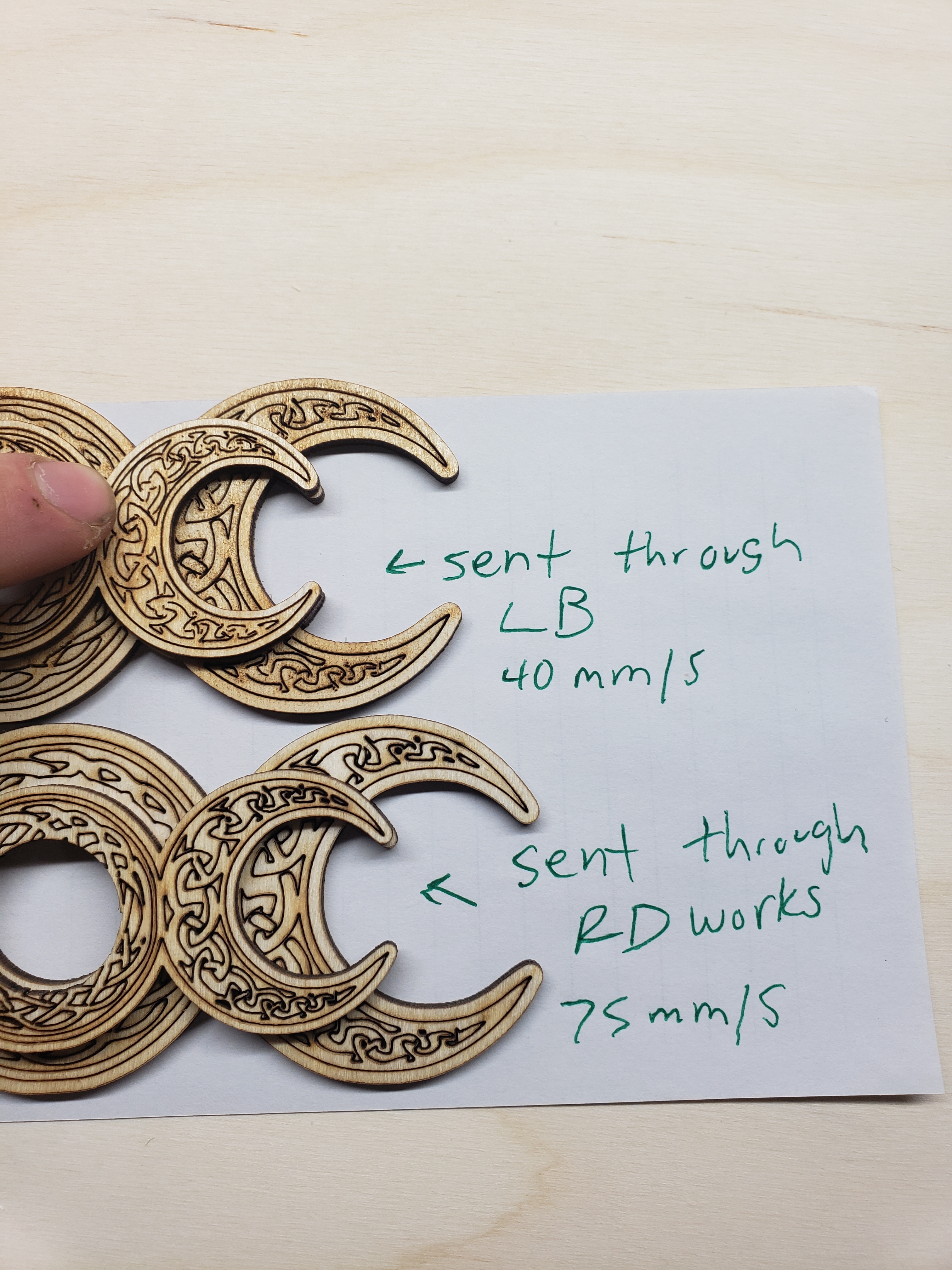
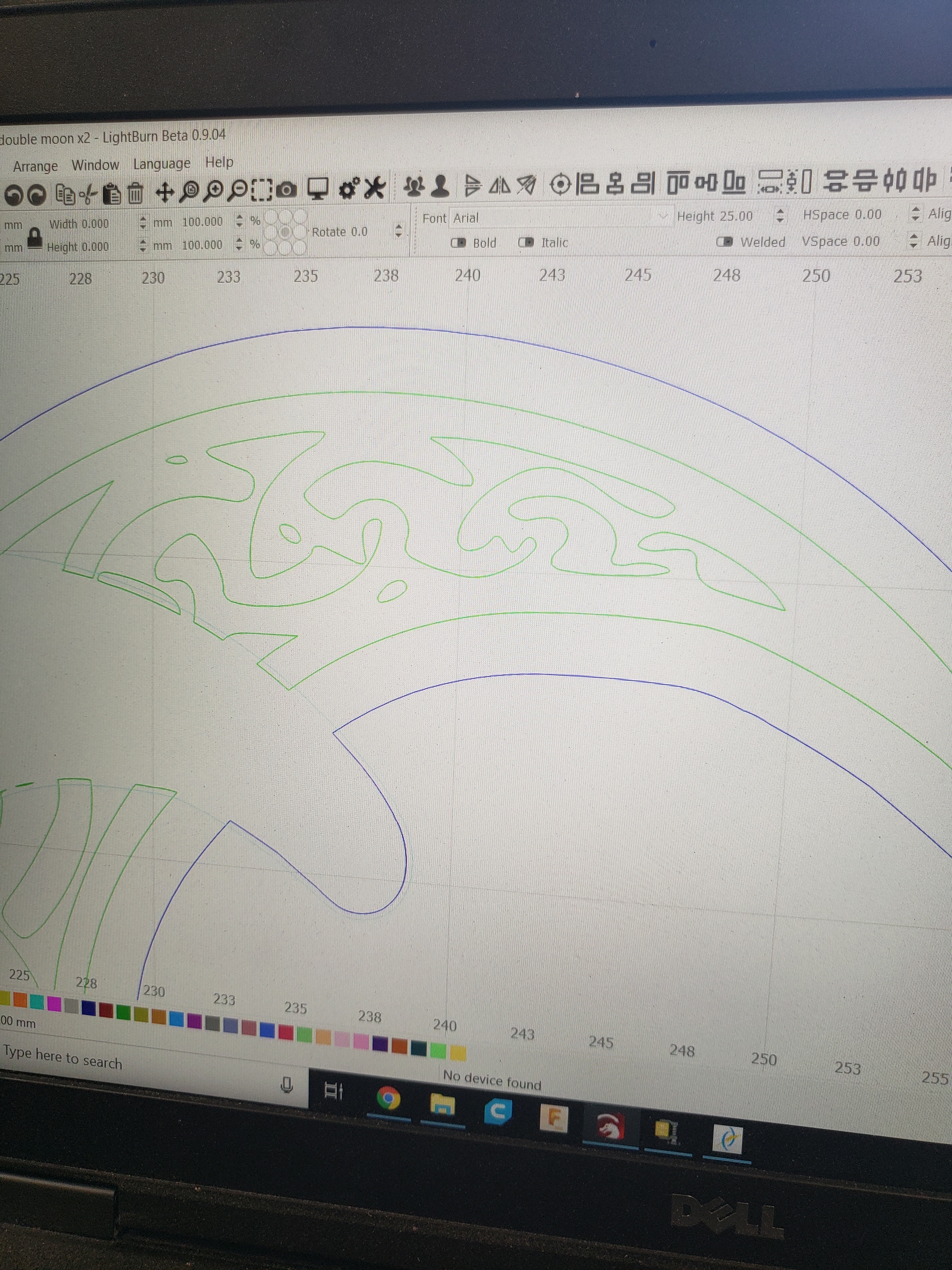
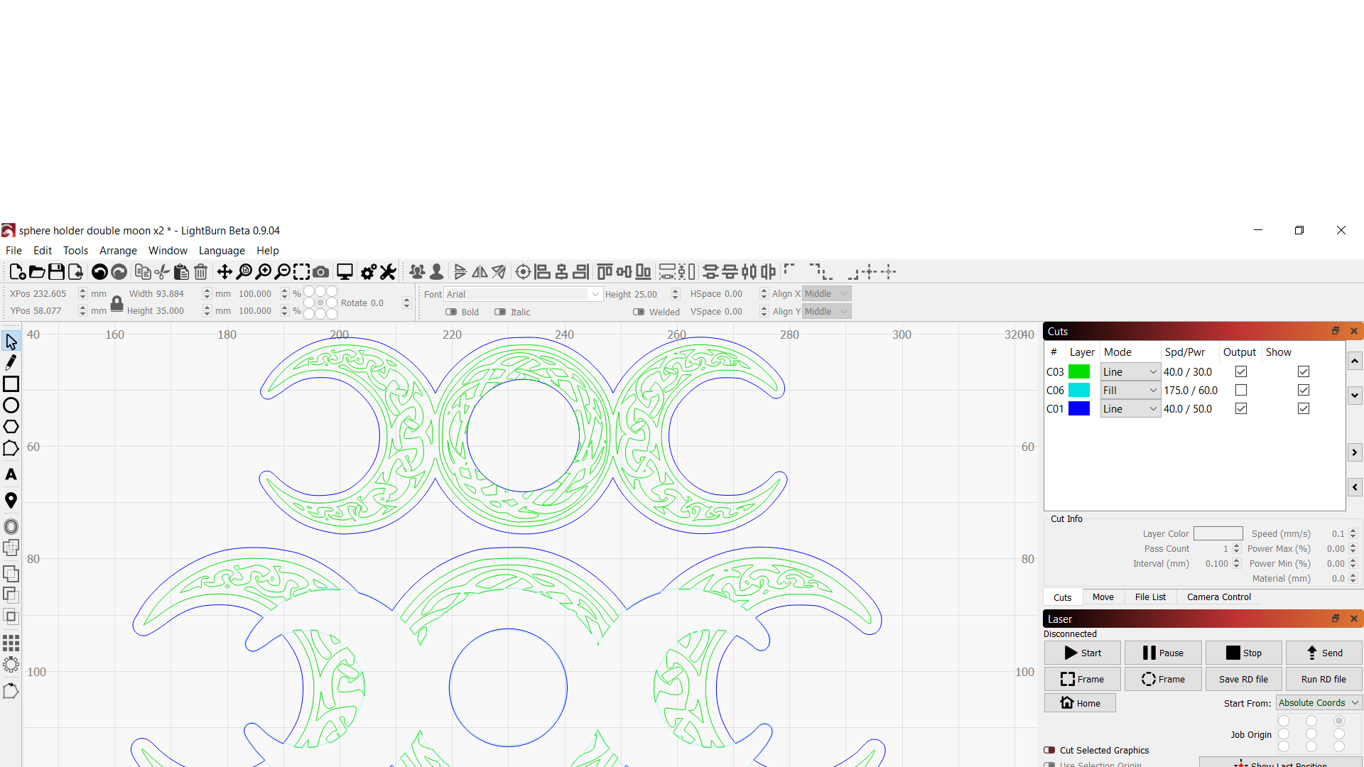
Looks like the same paths, and they look like they are “jerky”, was this intended in your design? Please show 2 more images, a screenshot of the original artwork in LightBurn, zoomed in to show a close-up of the “jerky” path pattern (inside of the moon) and a screenshot of the ‘Preview’ window zoomed to the same.
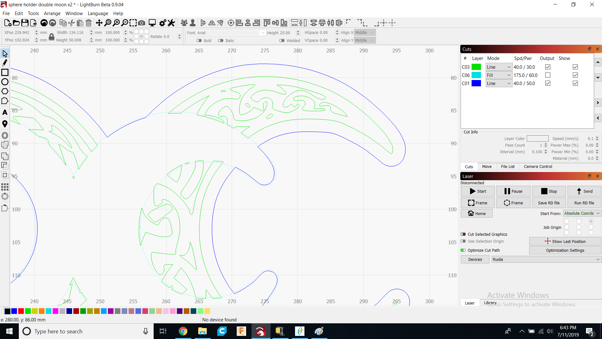
The ones from LightBurn look more pronounced due to what appears to be different power settings. Did you run the same min and max power settings for this test? Looks like the power was to low for the corner cuts in LightBurn.
Screenshots, not phone pictures as they are very difficult to see from our end. You are using windows…
I can see that and read that in your first post. This is why I asked if you used the same min and max power settings in both LightBurn and RDWorks. Did you?
I am trying to be of help, answering the questions posed helps me do this.
Thank you, yes there are easier for us to see. And you should be able to paste an image from the clipboard into the edit box of any post.
You still have not answered if you had the setting set the same for both LightBurn and RDW test cuts. But I would look into the ‘Min Power’ setting in LightBurn, double-click the layer to expose the ‘Cut Settings Editor’ window. I think you might have that set to low and the laser is not firing as it slows for direction changes.
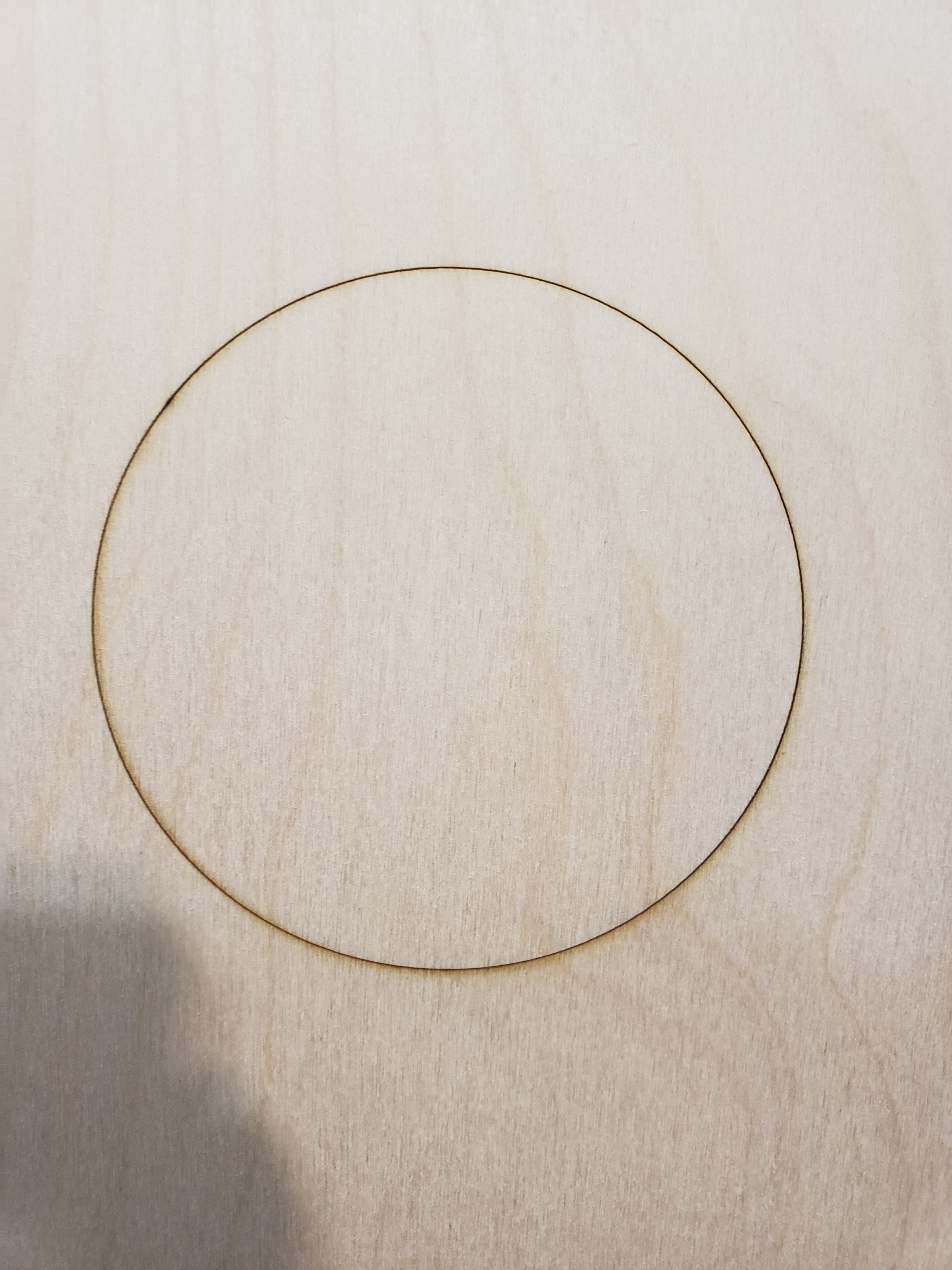
As for the “jerky” lines, you mention you have the same issue if you just run a simple ellipse or circle? You may be dealing with another issue here as well. Try this, draw a 100mm circle in LightBurn, set to ‘Line’ and run that at 100mm/s @ 30% power for both min and max. Let us see what that looks like and we can go from there.
it drew that fine. If I do circular frame it’s really jerky. Square frame is nice and smooth. Engraves it smooth. I put the matching min and max power and it looks normal now. Only thing is a circular frame that’s acting up. Any ideas? I’ll be testing more designs tomorrow and I’ll let you know if that fixed the vector lines for all.
Rubber-band frame on Ruida is jerky because it doesn’t go through the motion planner - each segment does a full stop, so that’s expected, and there’s not much I can do about that, sadly.
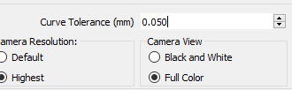
Try this in LightBurn: In the settings, reduce the Curve Tolerance number shown here to 0.025 and see if that helps.
And as Rick says, Min Power becomes important on Ruida hardware. You need to set that value to at least the threshold that the tube fires (usually about 10% of your rated wattage) or the beginning and end of cuts may not fire the laser properly.
I just received a Thunder Laser controller, and they have a few firmware differences compared to a standard Ruida that I’m going to be looking into over the next little while, so hopefully this gets cleared up quickly.
Everything seems to be looking good now. Min power has to match for all cuts but not scanning then?
Chaninging the settings for curve tolerance didnt change much. Looking forward to hearing if you can solve this though.
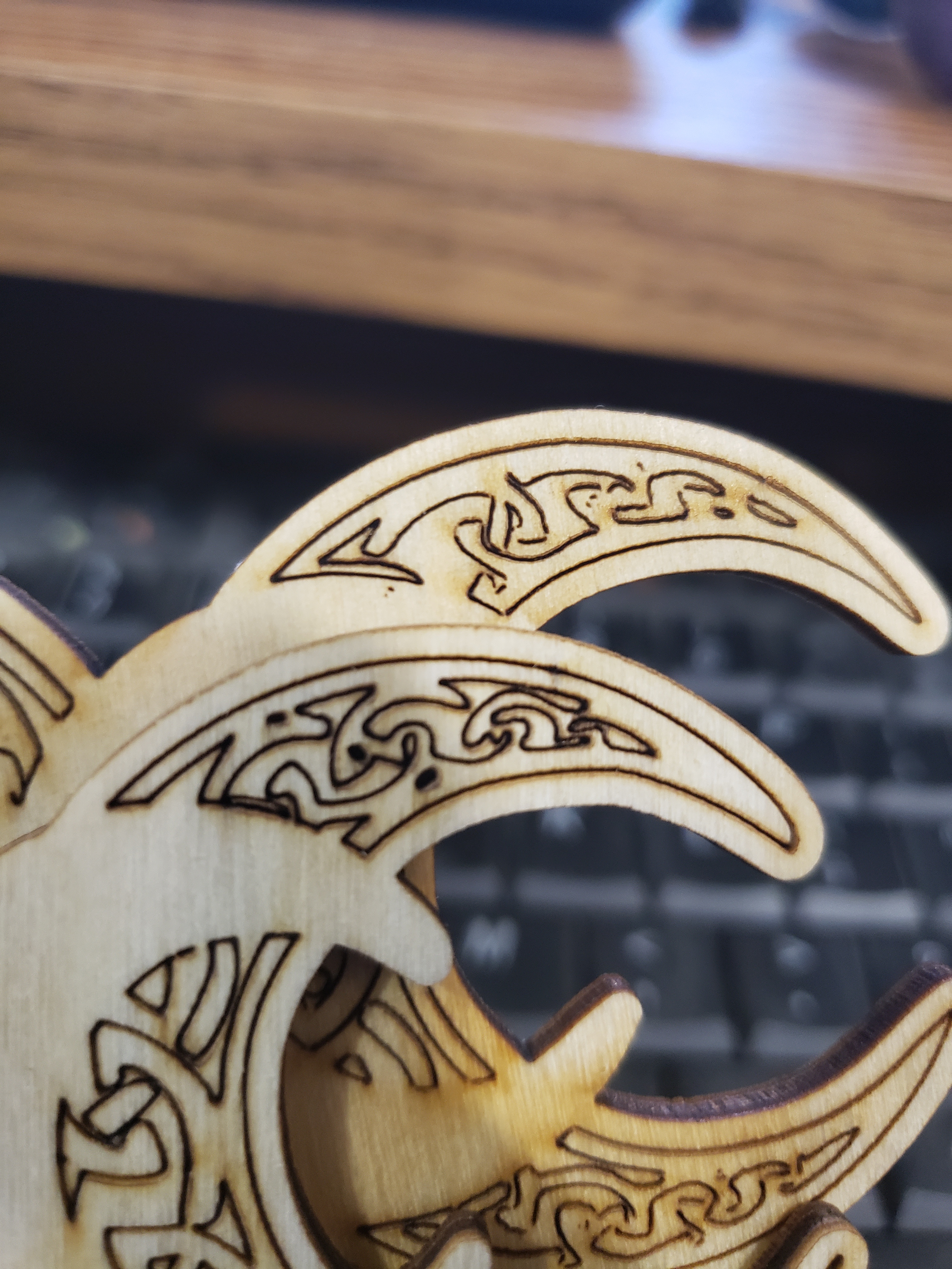
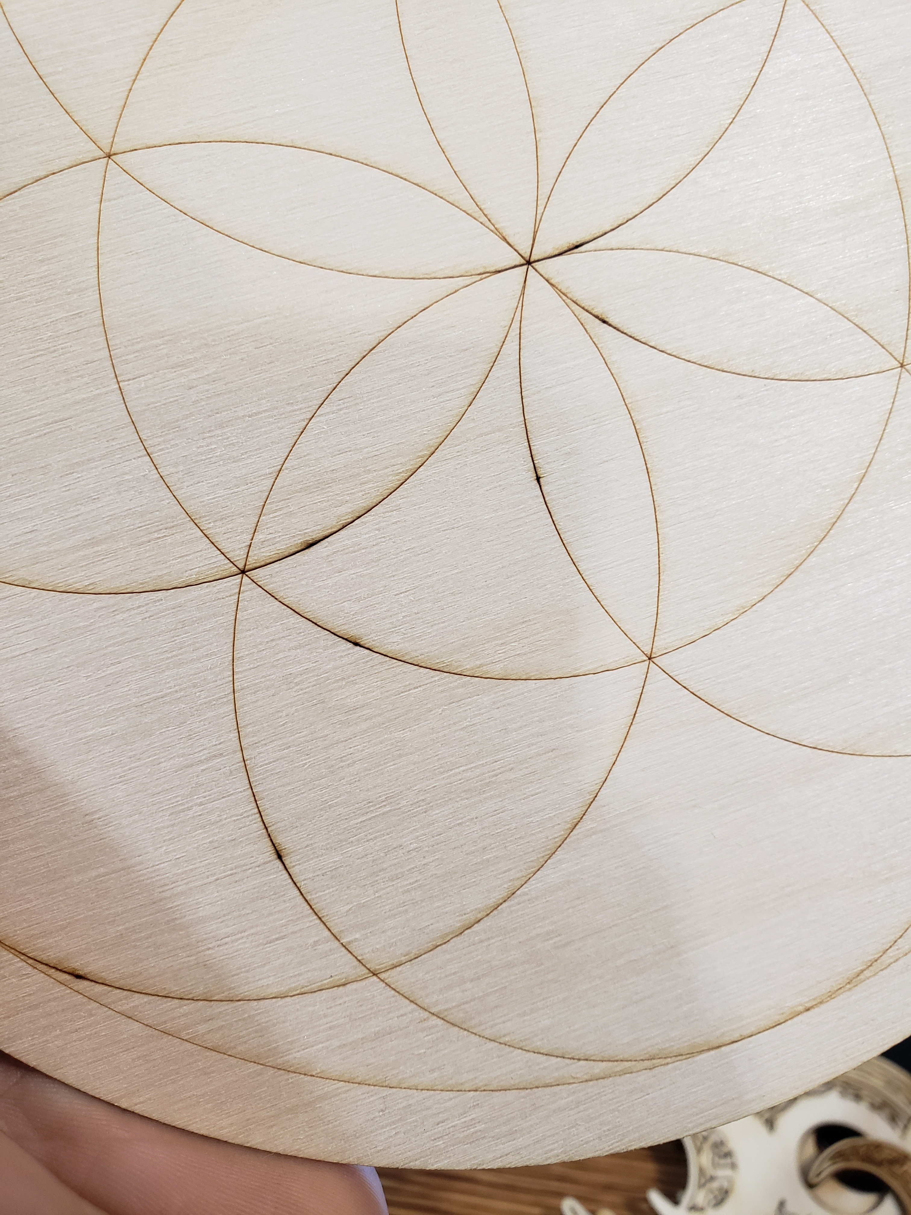
One more thing I’ve noticed is these entry and exit points leave a dot. Anyway to change this? (Not sure if I am supposed to ask about different problems as a new thread or just ask here)
That little button will let you pick where the cut starts.
EDIT: Shift-Click to reverse direction. Ctrl-Click to reset to default.
The dots are because you’re setting min / max power the same. When cutting, Min Power is used when the controller is going 10mm/sec or lower. Max power is used when going whatever speed you asked for, assuming it’s faster than 10mm/sec, and the controller ramps between them when accelerating and decelerating.
If you want the start/end points of markings like that to be clean, you need to set Min Power just above the firing threshold of the laser (probably 6% for a 60w, 8% for an 80w as a rough baseline). Otherwise you get a little “pool” of power from the laser being fired full blast while the head isn’t really moving yet.