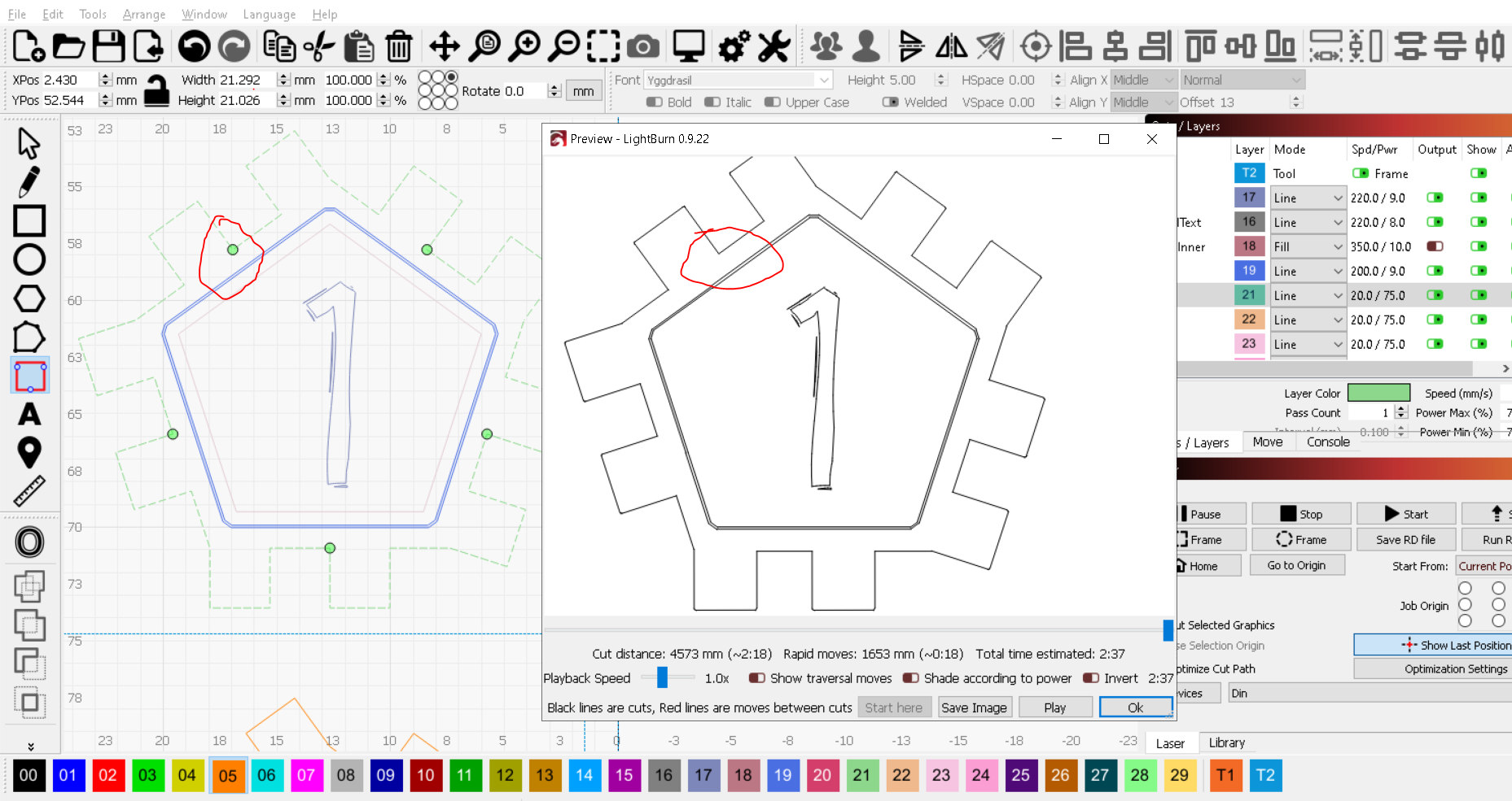
I’ve been having an issue where the Tabs/Bridges do not work when they are placed right in a corner of the shape. See attached image. I have a pentagonal box piece that I’m cutting out and I want it to have 5 tabs. Lightburn automatically adds the tabs exactly in the inside corners of the shape which for some reason makes them not appear in the preview, and not be cut by the laser.
If I change the number of tabs to something else like 3, then there is no issue and they display in the preview and cut properly. It seems like the algorithm that adds tabs breaks when it tries to start them on a corner.
As an aside, it would be amazing to be able to define the starting point when using automatic tab generation, so you
I can’t think of any reason that placing the tabs in a corner wouldn’t work, based on what I know about how they’re done. (@adammhaile wrote this feature)
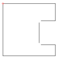
I have manual tabs placed in corners here and it’s working:
What’s your tab size in the Line layer settings? Can you see any gap if you zoom in?
@AlteriusOmega is that outline that you have the tabs on a single contiguous shape? Basically, if you try to select it does all of it select or just part of it?
It’s possible that those corners are actually the “end” of a path in which case the tabs won’t render.
Could you upload the file here? I can take a look.
The Tab Size was set to 0.35mm but even if I zoom in a lot, I still don’t see any break in the shape.
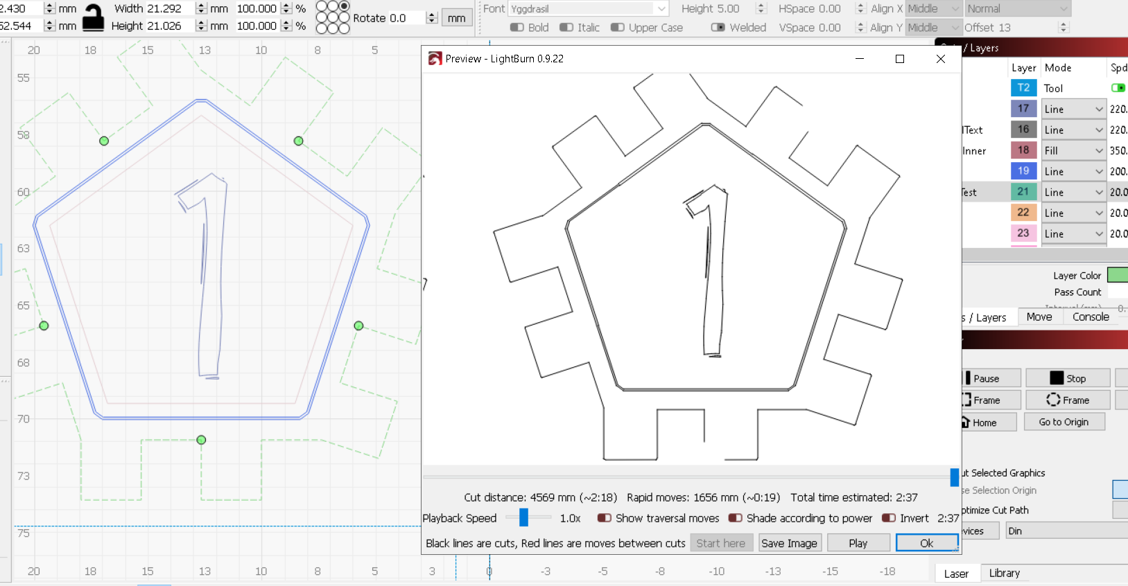
Strangely, if I increase the Tab Size to something crazy big like 2mm, I can see breaks in the shape in preview but they are not where they are supposed to be and there are only 2 instead of 5 which there are supposed to be. See attached pictures.
It’s definitely one continuous shape. The tabs were working fine with this shape when I was using 3 of them, but then when I changed it to 5 tabs I started having issues.
Ok, can you please upload the file in question here so that I can debug? I’m still not able to reproduce it locally. Ideally, save it in the broken state.
OK I will email the file to the support email and then update this thread with the results we find. BTW this is a test version of the normal file, so I’ve separated each of these pentagons into a different shape so I can try out different offsets to get the best fitment.
Thanks for sending the file - it looks to be a problem caused by the kerf offset you have applied. It knows the locations of the set tabs and when the offset is applied it has to attempt to find a close enough spot to place that tab on the new offset shape within a tolerance - for some reason that’s breaking down with tabs that are right at a corner in some cases.
My recommendation for now is to manually place the tabs since you didn’t want them on the corners anyways - or set a number of automatic tabs that doesn’t end up in placing them on the corners.
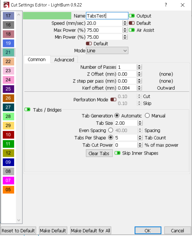
You don’t have to place all the tabs from scratch - just leave them automatic as you have now, select all shapes with Ctrl+A and then select the Add Tabs tool on the toolbar.
Then click and hold on the green tab dots you want to move and relocate them by dragging and releasing. They will then turn red to show they are now manual tabs.
I’m still working on trying to fix the base issue, just wanted to provide a solution in the meantime. It may be awhile until there’s a new release out anyways. I will also look into your request for being able to choose where the automatic tab insertion starts on the shape.
Thanks so much! I figured it was something along those lines.
I’m wondering if it would make more sense from a programming perspective to make the offset versions of a shape have the priority over the original shape. By that I mean that if a user applied an offset to a shape, then the offset version would become the one they would see on the grid (maybe the original would become dotted lines), it would be the one they applied tabs to, it would be the one they modified with weld and align functions etc. For all intents and purposes, the offset shape would replace the original shape completely in the program except for maybe a dotted line showing where the original one was. This would be more of a WYSIWYG approach. After all, the offset shape is the one that will be cut/engraved. This should avoid any issue of having to convert the positions of the tabs to the offset shape because the user would know exactly where on the actual offset shape they were applying them. Perhaps this is too big of a change or perhaps the side effects would be cause more issues than it would solve, but I wanted to offer a different perspective.
It’s not infeasible to do this, but it would be tricky because your source shapes are “live” - you can edit them with Edit Nodes, weld, booleans, type new text, etc, so we’d constantly have to update the offset version, which is expensive, and the nodes won’t correspond at all to the source (original) in any way.
Things like adding an outer ring around a shape (or a frame) will ‘flip’ the inside/outside state of a shape, so it’s not just one shape, but all shapes on the same layer, that would have to be constantly rebuilt as you edit, which has the potential to greatly slow interactivity if your file is complex.
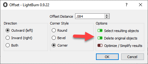
@AlteriusOmega - you could, however, use the offset tool on a shape and choose “Delete Original Objects”
That would pre-create the offset in the design for you. The disadvantage here is that using the kerf offset option is my more dynamic and you can change it easily whereas this makes the offset permanent.