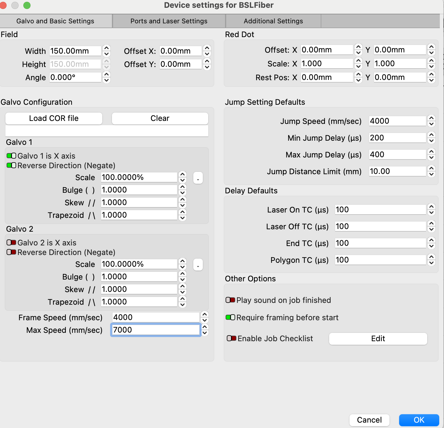
Hi, I’m trying to follow this article on adjusting for Scanning Offset in the device parameters. Now I don’t see such an option on my galvo laser device settings:
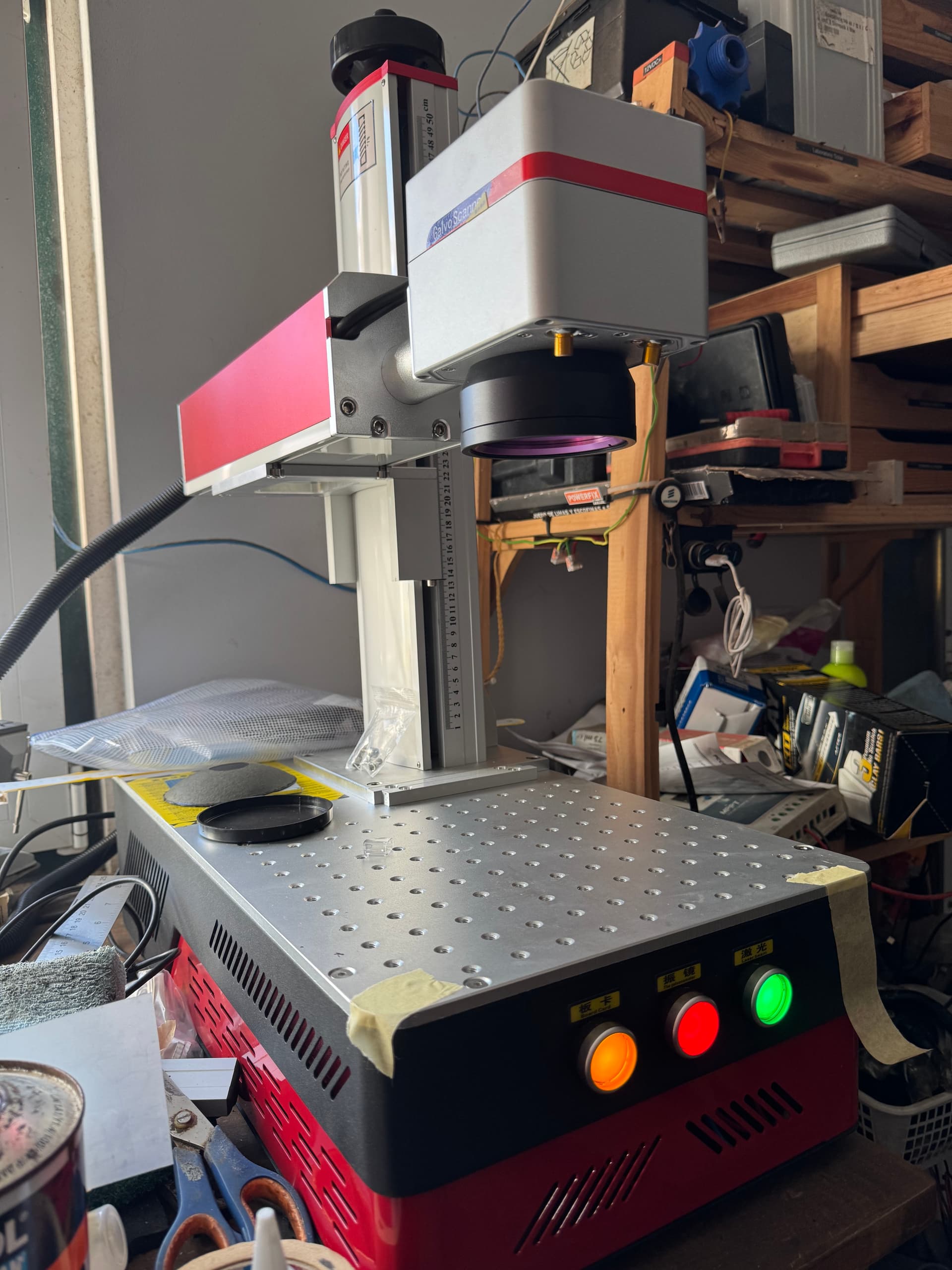
for reference: it’s a chinese galvo laser with a BSL card, with a JPT MOPA M7 60W laser source.
Maybe the adjustments are slightly different for this type of laser? I tried searching the forum for similar topics but couldn’t find anything that would be a close match.
EDIT: this is a brand new machine that I installed yesterday…I’m also a very fresh/newbie user of lightburn and lasers in general (but quite good with my CNC machine…already tackled that steep learning curve) currently evaluating it and thinking of purchasing its license
EDIT2: I’ve since found this great tutorial video on setting up timing and jumping parameters, which seem to address the finish quality issues I’m seeing. I’ve just finished preparing the calibration test files and I’m going to burn some metal business cards! I’ll keep the thread posted on how it goes
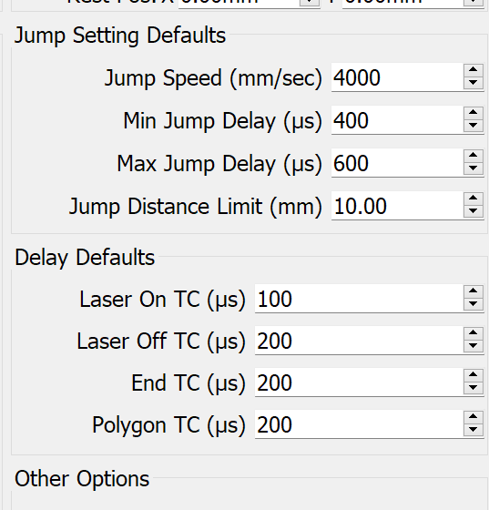
What I found is that the delay settings (Laser ON TC, Laser OFF TC, End TC, Polygon TC) have zero effect in my results…I’ve tried ranges from 0 to 5000 and I got zero perceivable differences between them (I looked under a 30x magnifier).
It’s as if these parameters are not implemented for this galvo laser option?
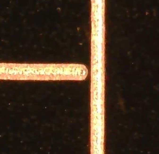
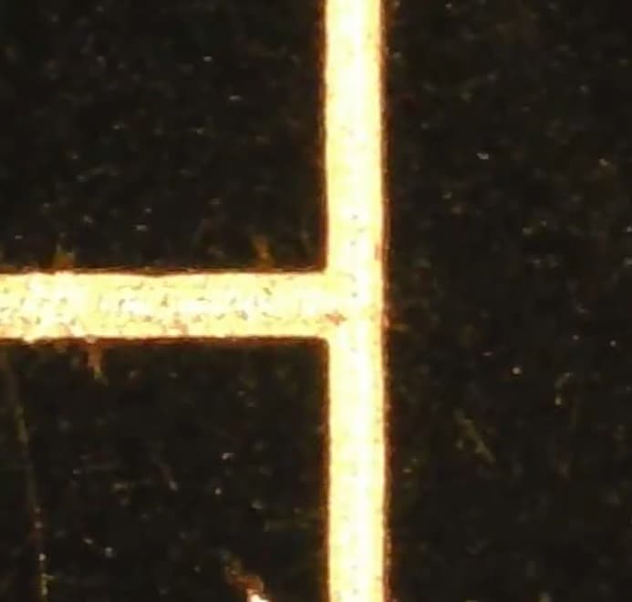
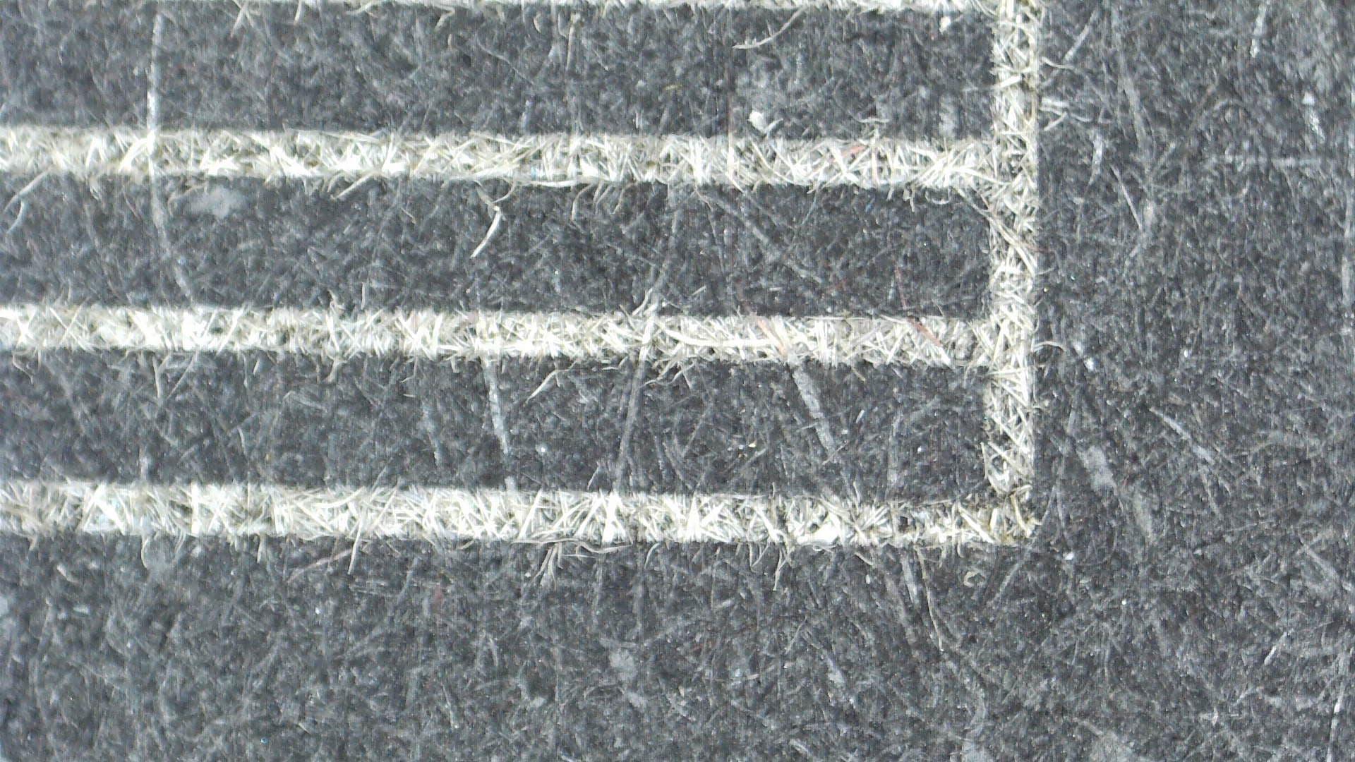
Anyway, the image quality has dramatically improved by just reducing the jump speed, at the penalty of longer run times…but I’m still getting a slight offset between the lines as you can see on my last image…any ideas?
For reference, here’s what the machine looks like:
As far as I know, there is no overscan, this is done with the delays you’re fiddling with.
If you think it doesn’t make a difference, since you have the values, zero them all out and re-run this test. If you get no change, we’ll have to go to higher ups that know the device…
Jump speed, as far as I know only works when the machine is moving larger distances with no active lase.
I’ve already done that test: zero all the TC parameters out, the results come identical if I set them all to 5000 (BTW I’m using the layer specific parameters to set these…not the global parameters, if this is relevant for debugging purposes)
BTW: the machine came with a sloppily organized USB drive, I’ve uploaded the contents to Google Drive here
I tried importing the SEACad config file (there’s also a few EZCAD2 folders in that drive)…maybe someone skilled at looking at these files can find a clue
That LaserEverything video is a great resource!
It’s worth watching the entire thing before you actually change any settings.
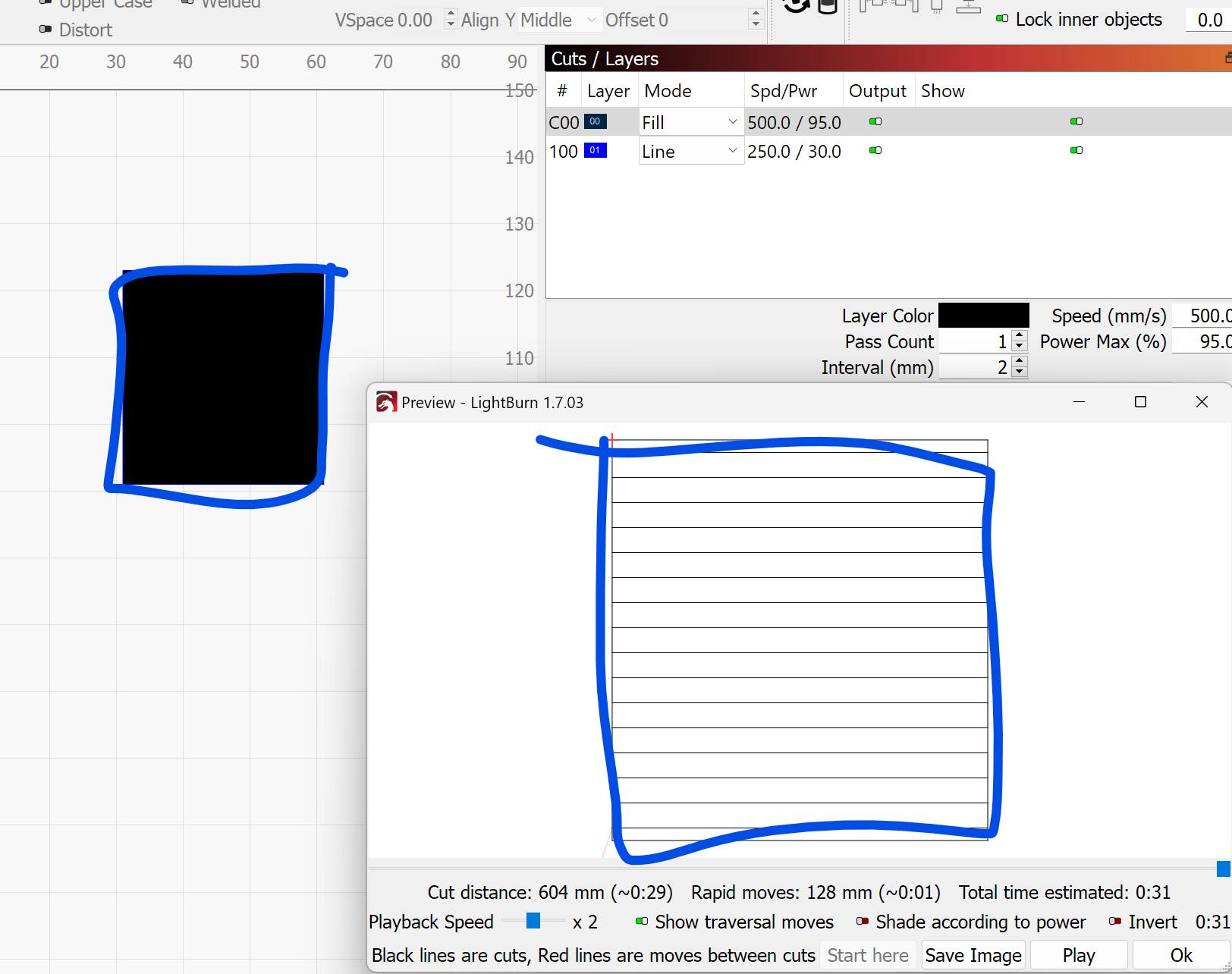
Since LightBurn does not have the “Mark Contour” setting, in order to see where your scanning lines start (Laser On TC) and end (Laser Off TC), you need to also engrave the bounding box of your fill layer by using another layer of the same shape but inSublayer Line mode:
The desired value will be more in the range of -1000 and +1000.
Also, make sure, you are using a reasonably high speed, so you can see the differences. They are using 1000mm/s in the video.
I downloaded these folders - The only relevant one is BslAppSimple5.2.2.1005.temp as the other ones are for EZcad. Both the BslCAD.cfg and LmcPar.cfg files don’t contain any info about the timing settings that could be imported by LightBurn as far as I can tell.
Personally, I would consider, asking your manufacturer to send you a config file to load into LightBurn to give you a better starting point.
Thank you so much for your detailed and insightful reply—I really appreciate it! I’ll go through your suggestions step by step:
I’ll try engraving the bounding box on another layer in Line mode to better observe how the Laser On/Off TC parameters behave.
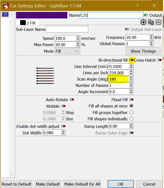
I’ll also disable Bi-Directional Fill and Cross-Hatch for now to ensure I’m getting clean, consistent left-to-right scanning.
I’ll stick to a higher speed like 1000mm/s, as mentioned in the LaserEverything video.
I’ll also see if I can get a proper LightBurn config file from the seller, though communication with them has been a bit patchy due to language and cultural barriers. I’m not too confident they’ll be much help, but I’ll try.
I’ll test everything you suggested and report back with my findings. Thanks again for taking the time to walk me through this—it’s been incredibly helpful!
I’ve completed a calibration test iterating over the Laser On TC and Laser Off TC parameters, with a jump speed of 1000mm/s (attaching the job file for clarity), and I’d appreciate your input on interpreting the results.
What I Observed:
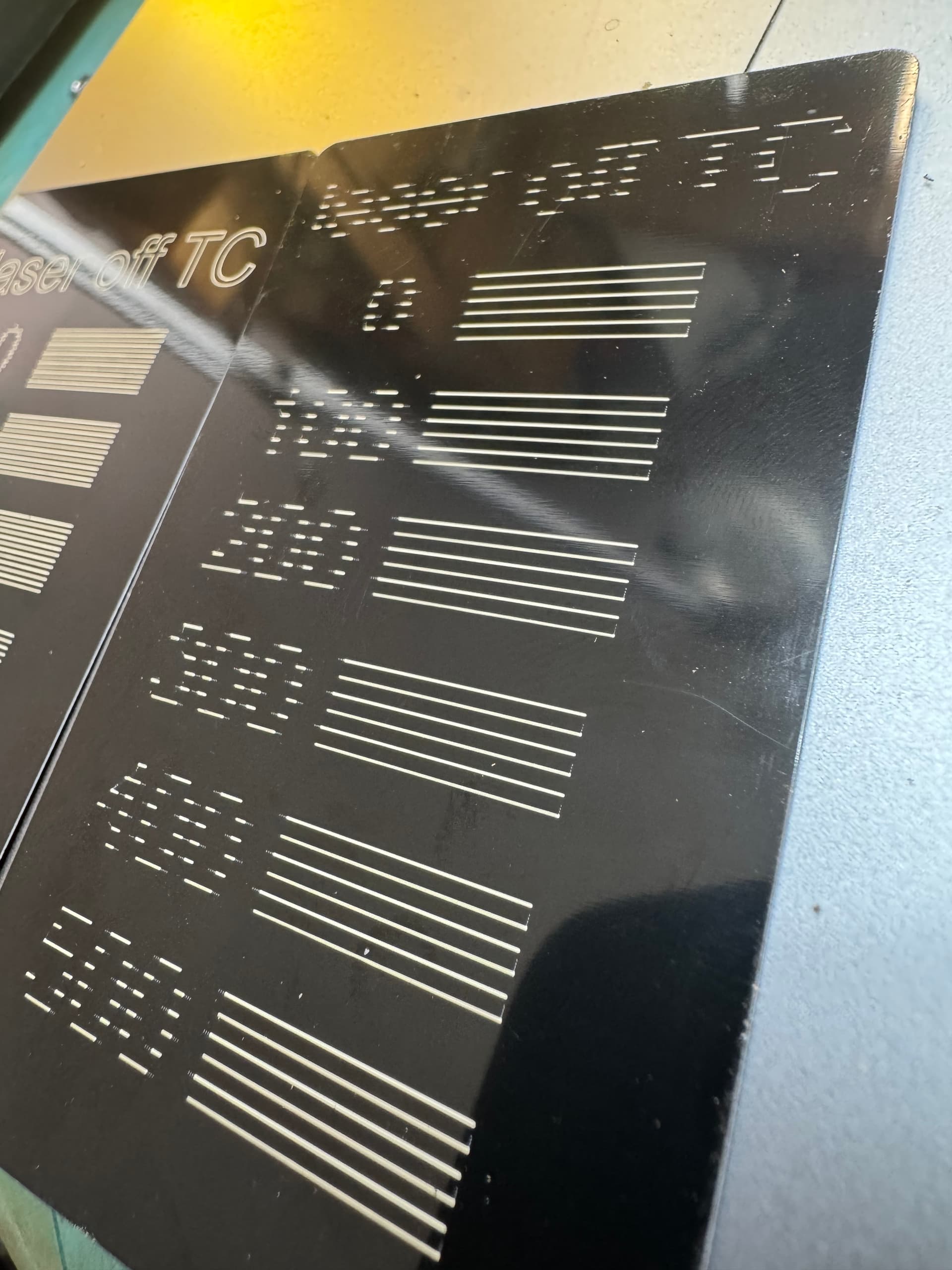
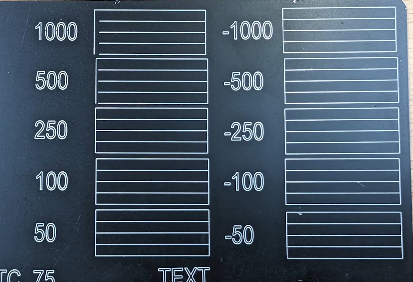
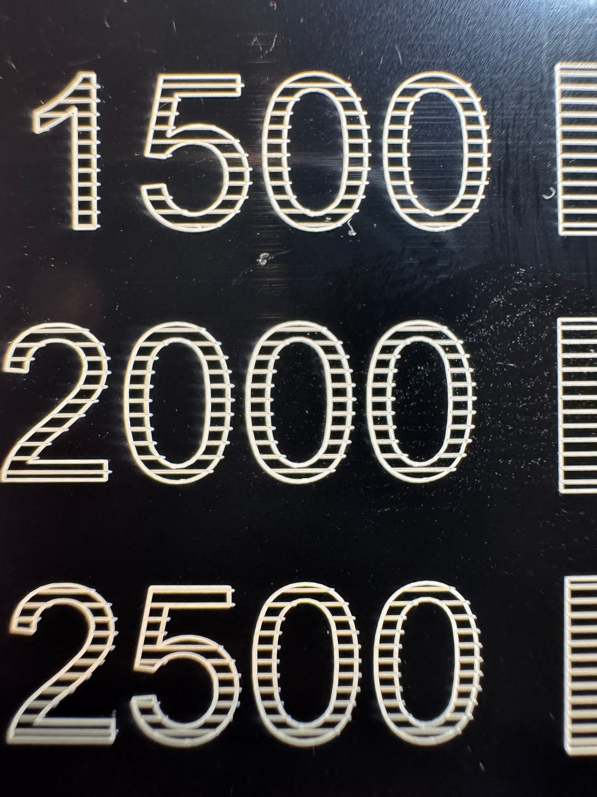
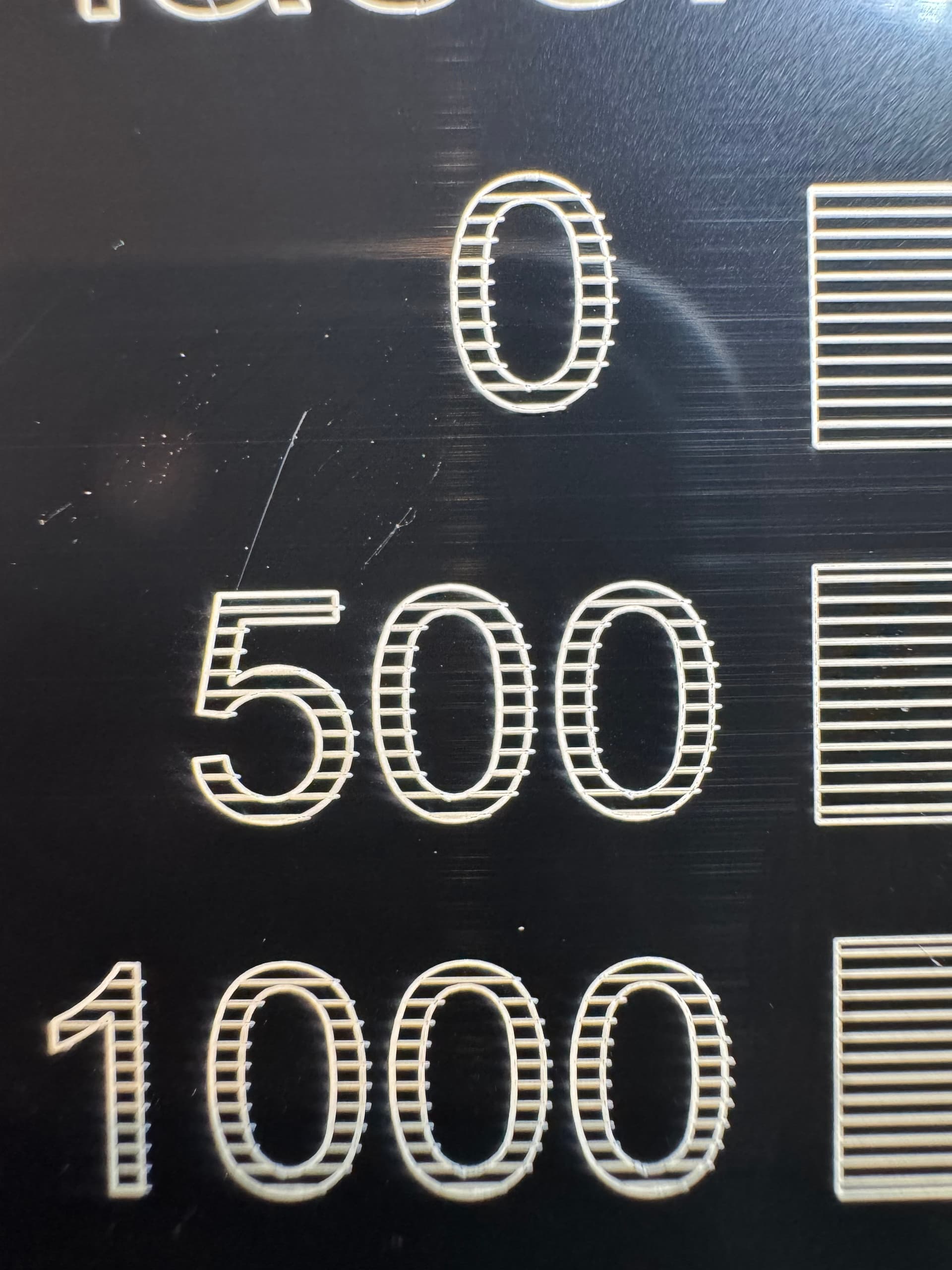
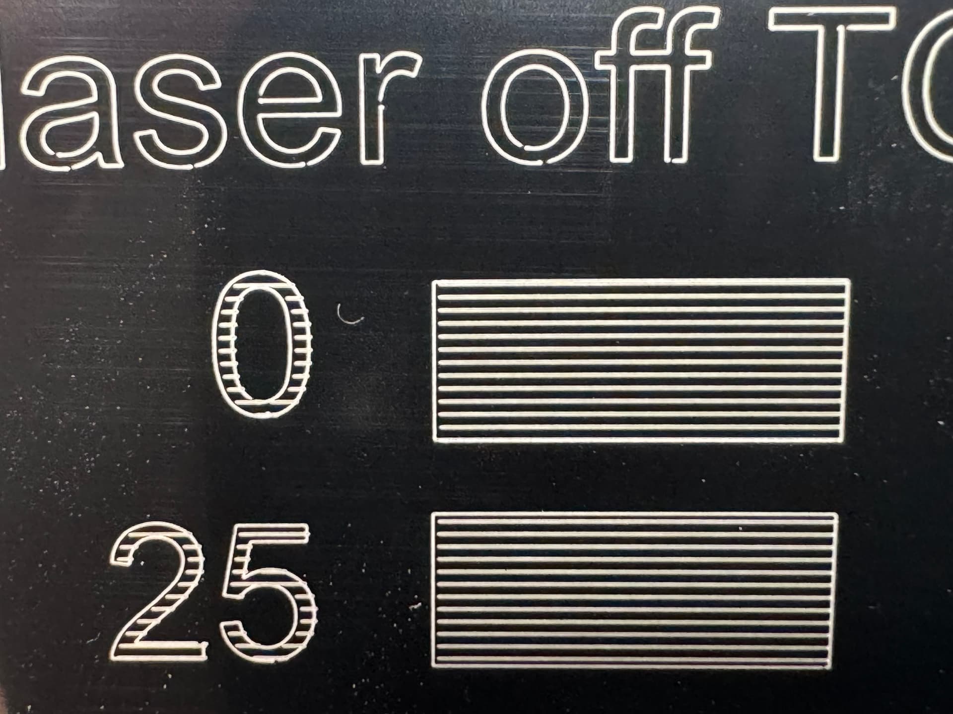
The tests were designed to evaluate the start-point behavior and end-point behavior of horizontal lines at intervals (0, 500, 1000, 1500, 2000, 2500).
Laser On TC appears to perform best between 0 and 500. Values above this introduce a noticeable gap between the bounding contour and the horizontal lines.
For Laser Off TC, iterating between 0–2500 does not seem to impact the overshoot of the horizontal lines to the right of the numbers (text patterns).
The overshoot is also absent from the rectangle outline patterns, which makes the results inconsistent.
I expected consistent control of the line ends across both the text patterns and the rectangles, but that is not happening.
Given these findings and using the LaserEverything tutorial video as a reference, I’m unsure how to interpret the behavior of the Laser Off TC parameter.
Do you have any insights into why this discrepancy might be occurring? Let me know if you need additional details or further tests.
Thanks for your help!
Best regards,
Miguel
EDIT: I’ve rewatched the LaserEverything tutorial video and found that he was able to set a negative value for the Laser Off TC parameter, whereas LightBurn only allows for positive values for this parameter. Could this explain why I can’t tell LightBurn to switch off the laser a bit before the line sweep ends? laser off TC calibration2.lbrn2 (71.0 KB)
That’s a good start. I recommend doing some more tests in between these values to determine the perfect setting.
You should not see an “overshoot” because the laser is supposed to only move until the end of the line. The fact that you still see it on the text might be related to the font you are using.
Instead, if you look closely at the rectangle, you should see a stronger burn mark at the end because the laser stays on for longer. (The effect of this might be more visible if you engrave with a higher power.)
The Laser Off TC can’t be negative by design. It does not make much sense to turn off the laser before it reached the end of a line and I don’t know why EzCad3 even offers negative values there.
You are looking for a value, where the lines are juust touching and meet at a nice right angle. In the video, this is at a Laser Off TC of 50us, clearly too early:
I’ve just ran your file, here are the results, now it seems that the Laser On TC is set too high at 0!
It seems however that Laser Off TC is best set at 0, but one key aspect is that it is not influencing the horizontal, left to right fill lines, but it is influencing the bounding line! it’s as if the parameter is implemented for the Line operation but not for the Fill one!
One key difference in your test file is the marking speed is set to 1000mm/s (10x higher than in my previous attempts, where I used 100mm/s)
Progressing further with the tests: I’ve created a new test file based on yours, where I’m iterating Laser On TC negative values, here’s the file for reference: laser om TC calibration-negative.lbrn2 (65.8 KB)
and the results (it seems the sweet spot lies in between 100 and 250):
Thank you for the tests and the feedback @mgomes !
That would confirm my assumption that the higher engraving speed of 1000mm/s make the effect more visible.
The Laser On TC can be negative!
A Laser On TC of -1000us means: the laser fires, waits for 1000us, then starts moving the galvo mirrors.
The effect is barely visible, but you can see the burn-in at the start of the line:
As with the other timing values, you are looking for a value where the lines meet at a nice right angle. - For the Laser On TC, look at the beginning of the fill-lines. - For the Laser Off TC, look at the end of them.
Here is a testcard I ran on a 20W Galvo with a “RAYCUS” Fiber Type:
Thank you for your detailed response and for explaining the behavior of the Laser On TC parameter. I’ve conducted additional testing and would like to share my observations for further clarification.
In my experiments, I noticed a discrepancy in how the Laser Off TC parameter behaves between Line and Fill modes:
In Line mode, the Laser Off TC parameter produces a noticeable effect, as expected.
In Fill mode, however, the parameter seems to have no observable impact. For example, horizontal left-to-right fill sweeps consistently terminate at the same point, regardless of the Laser Off TC value.
To illustrate, here are some examples from my testing:
Laser Off TC set to 0: No gaps are visible in the text or bounding box lines, and no differences are seen in the horizontal Fill lines.
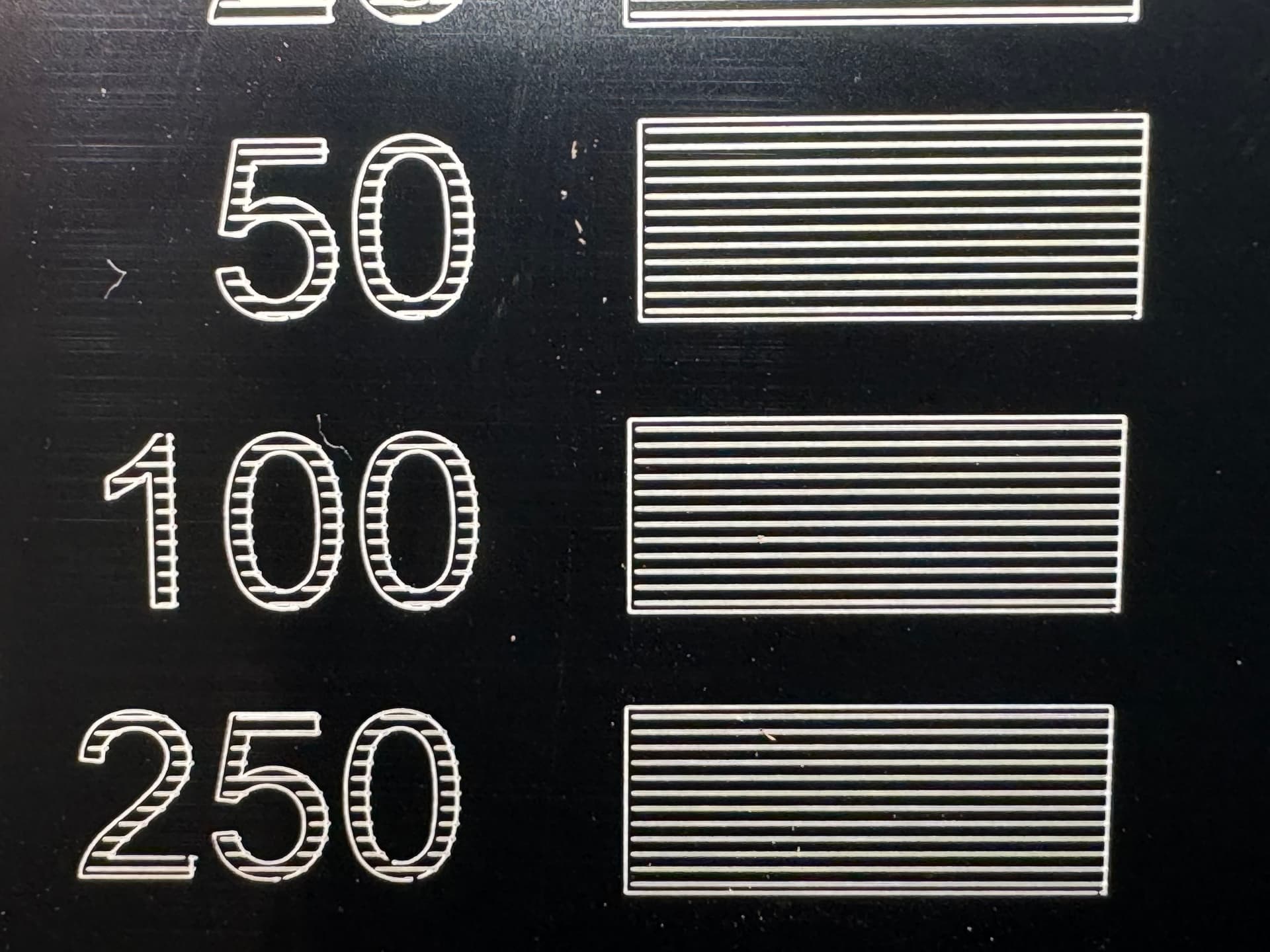
Laser Off TC set to 25, 50, 100, 250, 500, and 1000: As the value increases, the gaps in the text and bounding box lines grow wider. However, the horizontal Fill lines remain unaffected, with no observable differences between these settings.
This suggests that the parameter is functioning as intended for Line operations but is not fully implemented—or is behaving unexpectedly—for Fill operations. Initially, I concluded that the Laser Off TC had no impact on Fill mode. However, upon closer inspection of the images, I noticed that at higher values (e.g., 500 and 1000), the horizontal Fill lines slightly exceed the bounding box on the right.
That said, I’m still puzzled by the inconsistency:
Why do horizontal Fill lines extend beyond the text bounding line but not the rectangle’s bounding box?
Could the font truly be influencing this, as you suggested? If so, I’d appreciate a deeper explanation, as the relationship between the font and this behavior isn’t clear to me.
As I’d expect, the preview functionality within LightBurn shows no odd discrepancies between the text and the rectangle fills, this hints at a deeper problem with how LightBurn treats the text and the rectangular shape fills at a later stage, when the paths are translated from “LightBurn native” to “Galvo language”:
I think I’ve been able to further narrow down the root cause by doing another simple test:
I took your latest test file, and inverted the graphics horizontally (so that the numbers appear on the right side of the print) and an interesting pattern emerged…the horizontal fill lines now extend past all outlines(starting by the rectangles, which now lie on the left!) and all but the right-most shape/number!
This tells me that as the laser head is scanning through each fill line sequentially, it is dragging/shutting off too late except at the very end/right-most extreme.
Having stated this, do you know of any parameter that could be affecting this behaviour?
Best,
Miguel
EDIT:
Progressing further with the tests, I’ve made another change to the original test file: change the fill mode from “Fill all shapes at once” to “Fill shapes individually” and the results are interesting:
the results, notice how each shape is now affected, if an individual shape has a gap/empty space in the same horizontal line, like a “0”, the left portion of the horizontal fill line is affected, but not the right-most one):
I recommend you look carefully at the Preview to see the order of the engravings.
I agree 100%, selecting “Fill Shapes Individually” makes sense for these test cards!
Did you leave your jump settings at these values like the video recommended?
I think what we are seeing in your last test cards is a combination of disadvantageous Jump timing settings and the End TC value. I didn’t get my head wrapped around the End TC just enough yet to make give a good explanation but we’re getting there! Here is the relevant section in the video
In the meantime, I found this newer video about Galvo Timings with an interesting approach for the test cards! https://www.youtube.com/watch?v=NdFr70yoRyA I will give this a try tomorrow.
So, using the calibration file from the MakrTheory video makes it easy!
What I stumbled across:
Make sure to actually change the Polygon TC in the “Line” sublayer!
Still not 100% sure, what the End TC does, but I set it at 200us for now.
For the Gweike G2 Pro 30W with a RAYCUS type and 150mm lens, I’m happy with these values:
I probably have the Jump Delays a little longer than necessary but I was aiming for precision over speed.