Thank you for looking into this. It’s interesting that the stepper motor coils are constantly energized when powered on. My unit exhibits the same behavior, but the rotary movement check fails to activate. I’ve double-checked my settings against the rotary setup instructions, and everything appears correct. I’ve contacted Commarker support to compare my unit’s behavior to a known working one. They’ve been responsive and courteous so far, though I understand they typically reply within 24 hours. Fingers crossed for a solution. Thanks again.
That’s generally true as you don’t want it to change it physically or the controller loses what it is on the work piece.
All of my lasers have their steppers locked. Including the galvo rotary.
![]()
2 Likes
100% correct. When Microstep driver is powered coils are engaged. There are 2 ways around this, separate power on off for the power supply powering the microstep driver, or use the ENA pins on the microstep driver. They put the coils in neutral. Do not just unplug the rotary from the microstep driver when the driver is powered. (Or plug it in) Power down first. Supposedly hard on the driver.
I wired a button to the ENA terminals on mine.
1 Like
Words of wisdom… I admit it, but I’ve always done a hot swap, both fiber and co2 ![]()
![]()
1 Like
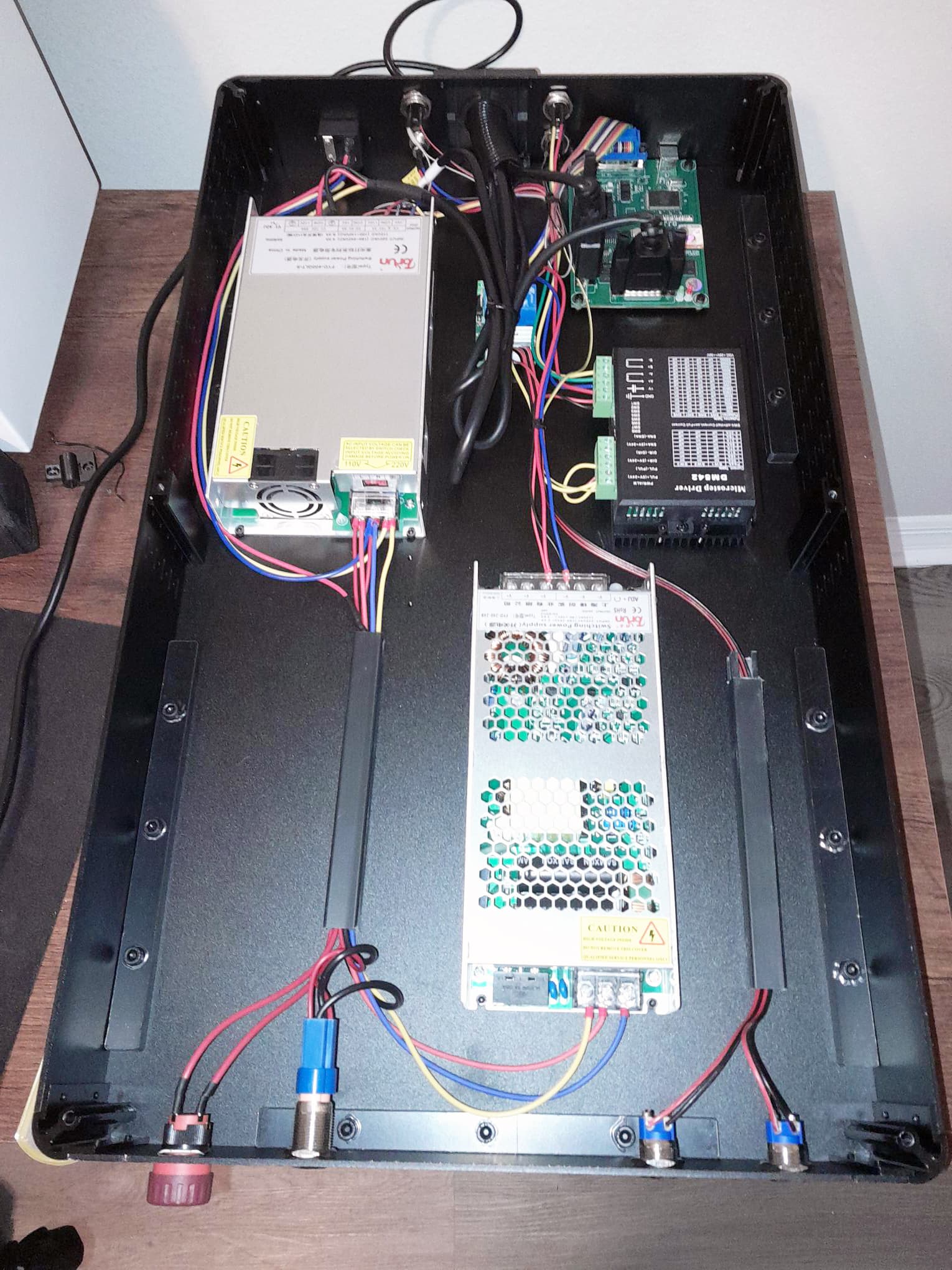
Troubleshooting my laser rotary issue. First, I replaced the microstepper driver and verified wiring continuity (including 5V/ground). The problem persisted: rotary stepper motor coils energized, but no movement. Next, I replaced the computer board. Now, the laser isn’t recognized by my computer at all (no device in Task Manager). Suspecting a defective board or power issue, I noticed squished wires due to mainboard connector height. The enclosure top cover seems to be pressing down hard on them. Tomorrow, I’ll reinstall the original PC board and test the rotary in EZCad. I’ll need to uninstall Lightroom first, as it conflicts with the laser driver.
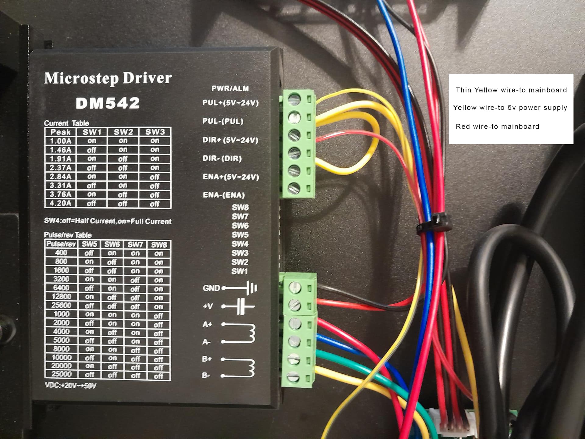
The driver looks miswired:
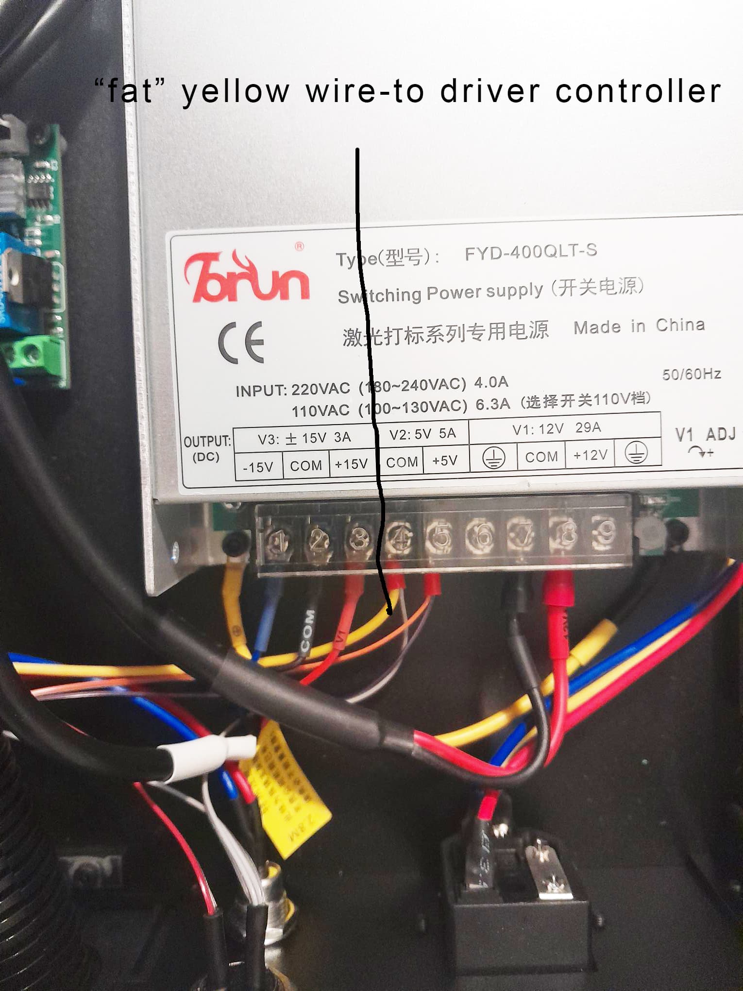
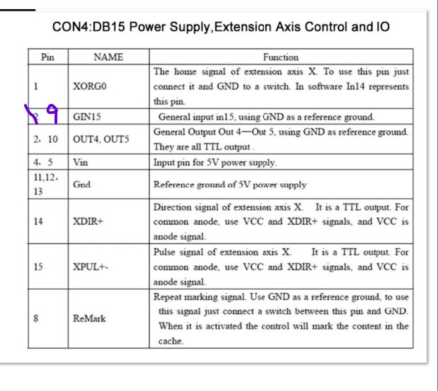
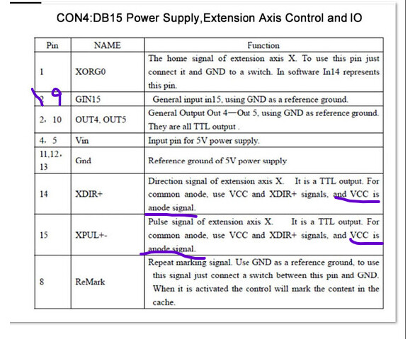
The fat yellow wire is probably +5 or +24 V from the controller, but it’s connected to both - terminals. If that’s what it is, then it should go to both + terminals, as indicated & labeled.
The skinny yellow and orange wires should go to their respective - terminals, not the + terminals.
1 Like
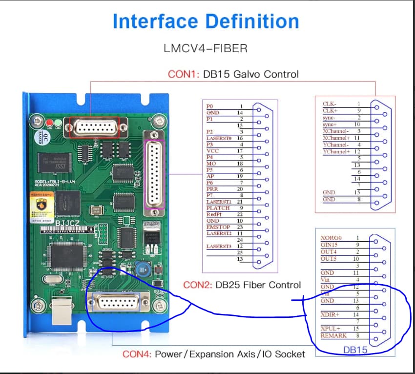
Thank you for your assistance. I’m trying to understand the wiring on this device. It arrived from the factory with this configuration
. I’ve replaced the microdriver controller, keeping the original wire arrangement. Now I need to connect two thin wires from the mainboard, a 5V wire, and a bridge wire. I’m completely confused about where each wire goes. Could someone please help me identify the correct connections? I’ve never dealt with this type of wiring before. I’ve attached two additional pictures for reference. Thanks!
OK, maybe I can help.
Here is my wiring,
If you notice, Positive is the common for PUL and DIR and the negative terminals are the individual signals for PUL and DIR.
My yellow common (+) goes to pin 4 on the JCZ board. The blue and white go to 14 and 15.
I don’t know what is the difference between yellow going to the 5V PS or going to pin 4. so maybe its is the just the 5V+ common going to DIR+ and PUL + on the driver.
If you watch Jeffery’s video below, 4 years old but his was originally wired GND pin 11 as common/ 14 and 15 as signal and didn’t work. changed common to pin 4, worked. Lot’s of info still relevant.

Same here if you turn the laser source off (keep the red dot) the rotary is without power too. Depends ofcourse on how all is wired
if the thin wires come from the controller it makes more sense the fat wire goes to ground thats why the wire bridge is there
Thank you for your help. Why is my “fat” yellow wire going to the power supply’s COM terminal and not the 5V rail? According to Al Fernandez’s posted picture, his controller is pulling power from the DB15 connector. My stepper controller is wired differently; it is supposed to get 5V(not COM)
from the power supply. Thanks.
Com is common ground for the 5V which I thought it would be as you have the two - terminals on your stepper driver together. Does make sense “common” the pin 15 is gnd too just different place where the gnd gets taken from. Your pin 15 and these yellow should be connected somewhere
‘COM’ on a power supply
is typically a common ground or reference point, not a positive voltage source. Stepper controllers require a minimum of +5V on the PUL+ (Pulse+) and DIR+ (Direction+) inputs to function correctly.
I’m puzzled why the ‘fat yellow wire’ on my controller is connected to COM instead of the +5V rail. This is incorrect wiring. As Ednisley and Al Fernandez correctly pointed out in their earlier posts, they never suggested connecting PUL+ and DIR+ to COM
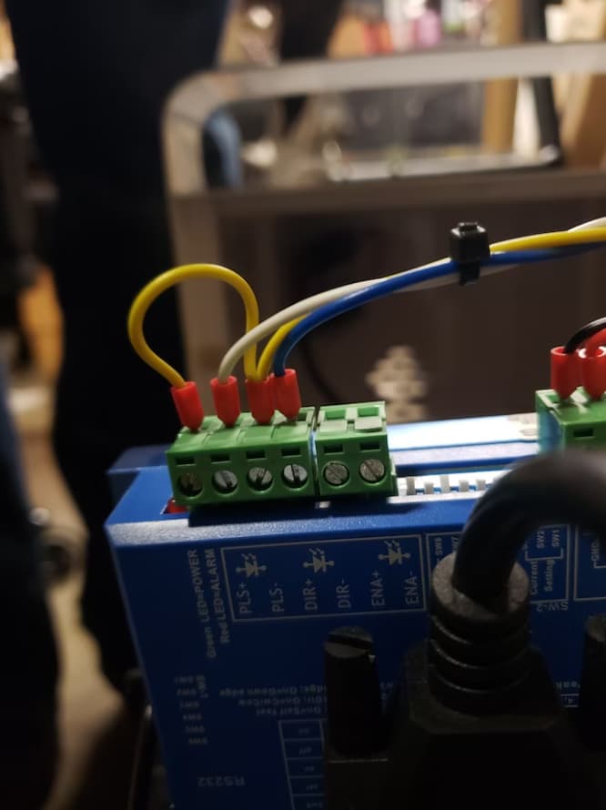
If this is the picture of yours? The thin wires go the + and the yellow wires to the - (com) all good I would say?
Progress Update: I’ve spent some time investigating the rotary wiring and attempting to correct the connections.I initially left the “fat” yellow wire ( PUL+ and DIR+) connected to COM. I then moved the thin red and yellow wires to PUL- and DIR-. This did not resolve the issue.
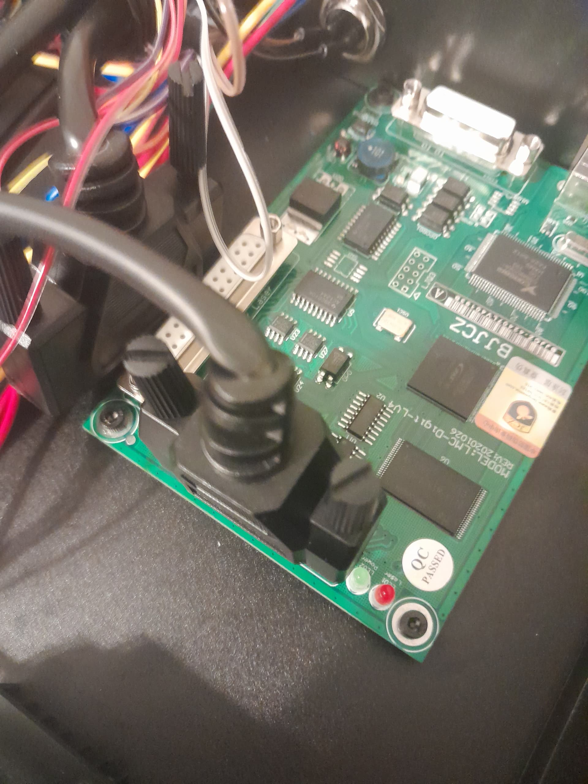
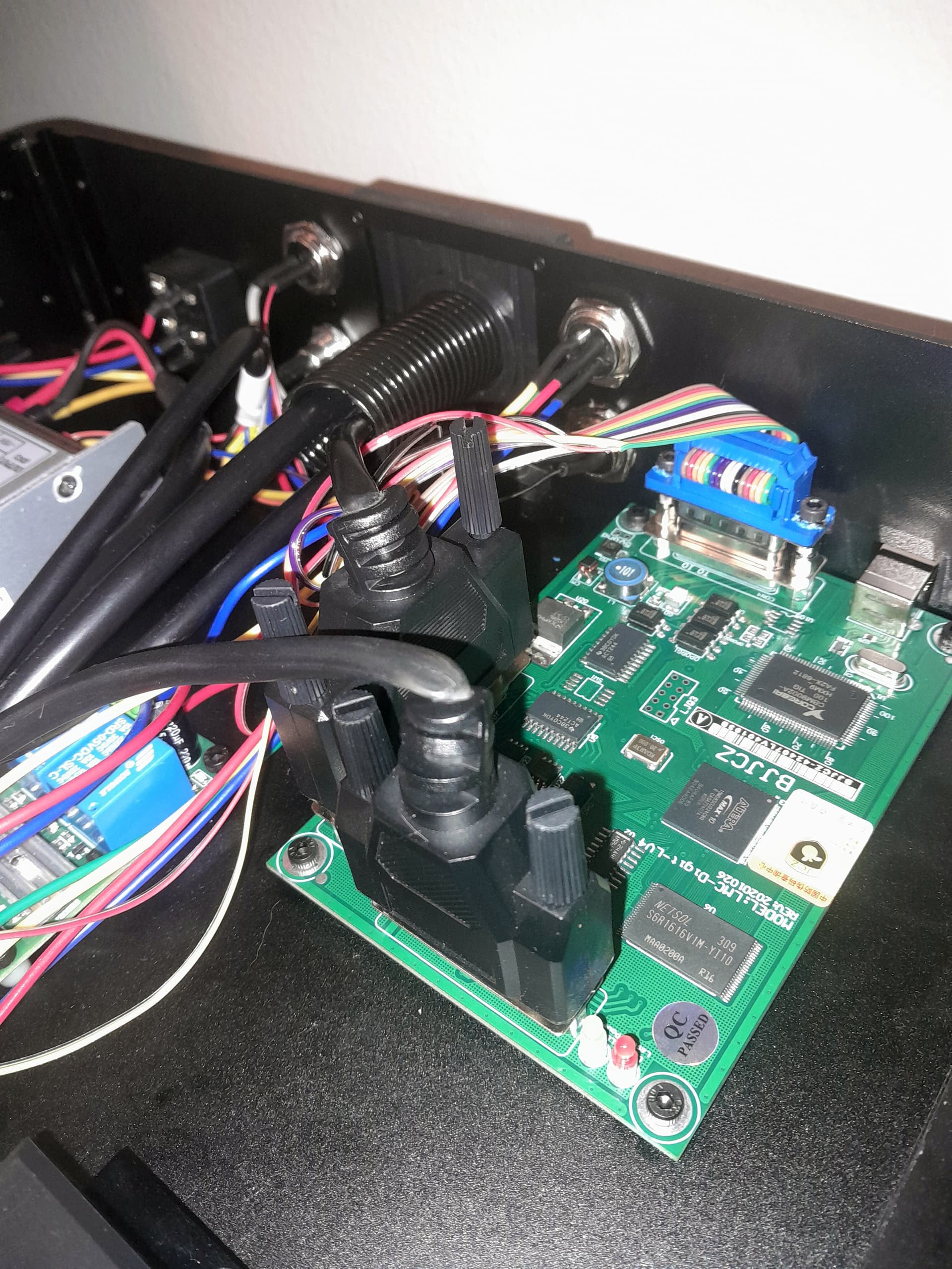
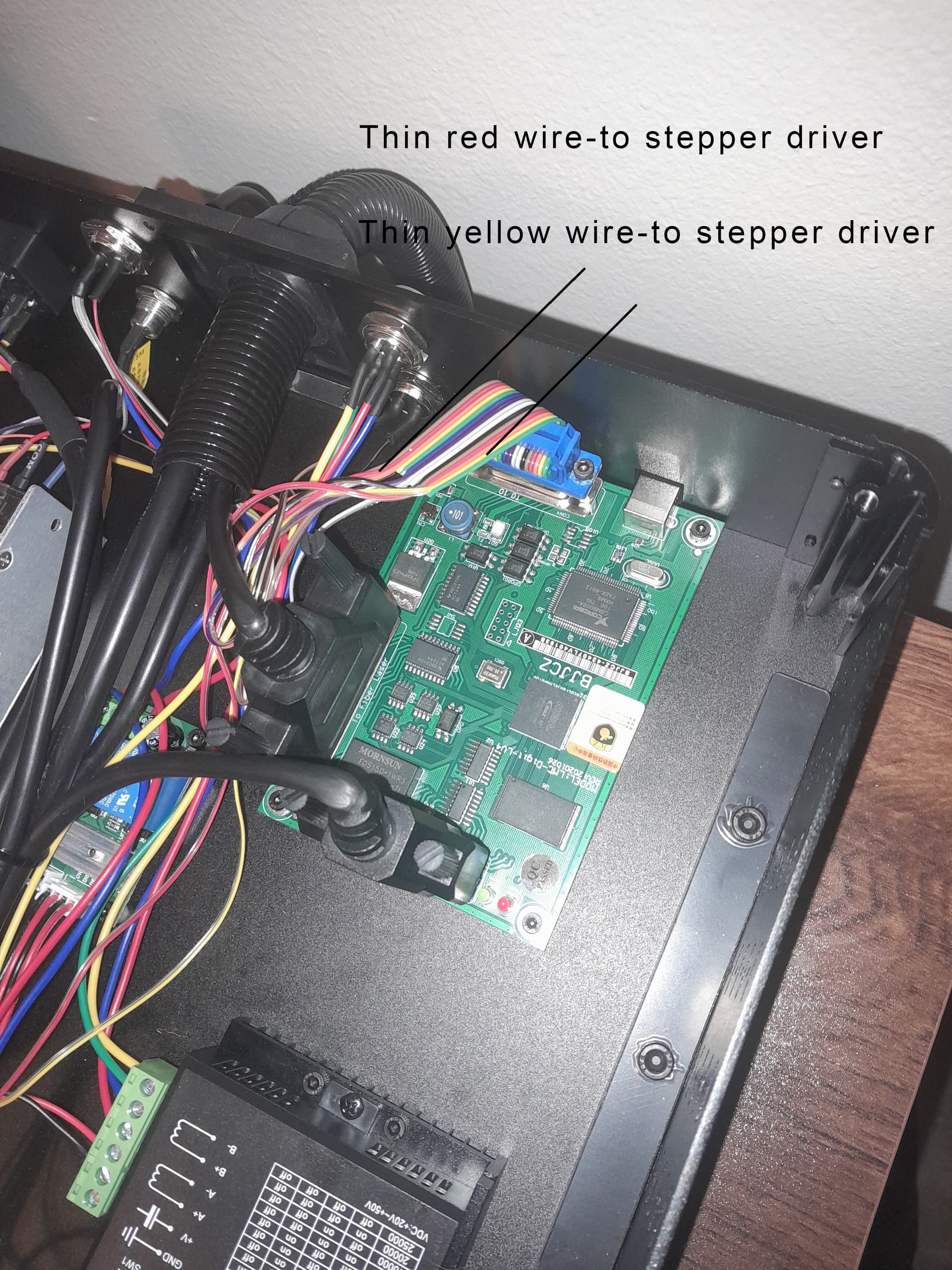
To further test, I moved the “fat” yellow wire to a +5V terminal on the power supply. Still, no rotary movement. I’ve also confirmed continuity between the thin red and yellow wires and their corresponding pins on the main connector. However, it appears my computer board might be a newer version with a different pin configuration, or the wiring may be incorrect.(see picture)
I’m currently unable to proceed and will be contacting Commarker customer support once more to request a fully functional replacement unit. This situation is particularly challenging as I have pending glass (round) etching orders that I’m now forced to outsource. I specifically invested in this UV laser for its superior glass etching capabilities compared to CO2 lasers. To add to the frustration, I’m financing this machine and making payments for a device I cannot fully utilize.
Thank you for your ongoing support. I will update you after I’ve communicated with Commarker.
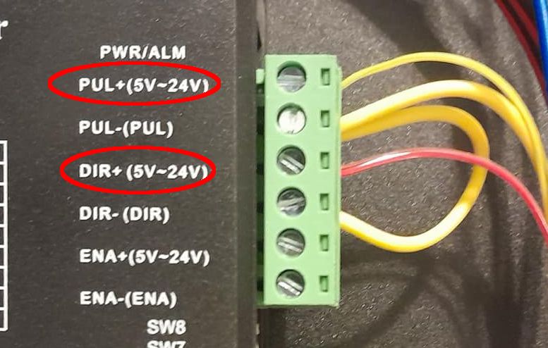
Fat yellow wire goes to pin 4 or 5 on the few working setups I have seen, (or probably the 5V power supply POS although I haven’t seen it done that way before), as directed in this image. Not common (NEG)
FYI Connecting a TTL output directly to ground can damage the board (or so I’ve heard) so be kind of careful with this.
Thank you very much for your help. At the moment, I’m beyond frustrated and I won’t take the machine apart for the 5th time. I will email Commarker and wait for them to decide what to do.
1 Like
Perhaps I’ll contact the LightBurn support team and ask if they can reach out to someone with the same Omni 1 laser and the original Commarker rotary kit. I’d like to see if they’d be willing to take their machine apart and provide some pictures of the correct wiring for me.
1 Like
I know the feeling! You just want a working laser, not a crash course in Anodes and TTL logic…
Keep us posted.
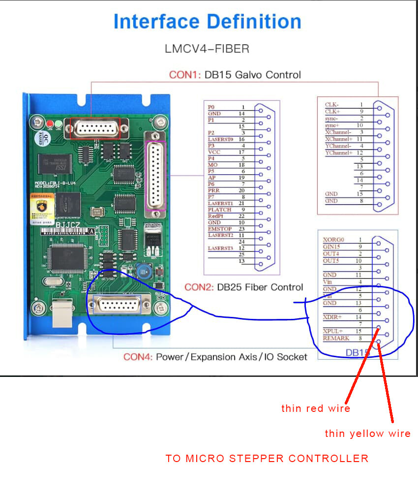
Either of those is possible, because the wiring as shown makes no sense whatsoever:
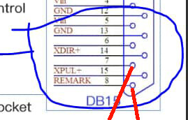
Based on that picture:
- The stepper driver wires (sketched in red) connect to nothing in particular
- The
XDIR+andXPUL+signals go nowhere
Of particular interest is the polarity of the stepper signals. I assumed that the controller outputs were ordinary / typical / standard low-active signals. That is incorrect, as they both appear to be high-active.
If so, then the original wiring at the stepper driver makes sense:
- The
PUL-andDIR-terminals connect to the fat yellow wire toGND(pin 13) at the controller DIR+connects toXDIR+(pin 14)PUL+connects toXPUL+(pin 15)
With that wiring, a high-active signal on the controller output will push current through the stepper driver input to GND as it should.
In all other machines, a low-active signal on the controller output pulls current through the stepper driver input from the +5 supply.
Now, it is distinctly possible the controller can be configured to invert the polarity of those two signals, in which case hilarity will ensue when you (try to) run anything.