If only one corner is misaligned, It would indicate that something went wrong during the lens calibration.
Are you aware that the camera doesn’t need to point on the bed during the Lens Calibration?
Holding the AprilTags farther away (or using a smaller card) can help ensure that every corner is captured correctly.
@Aaron.F what % should the result be at least?
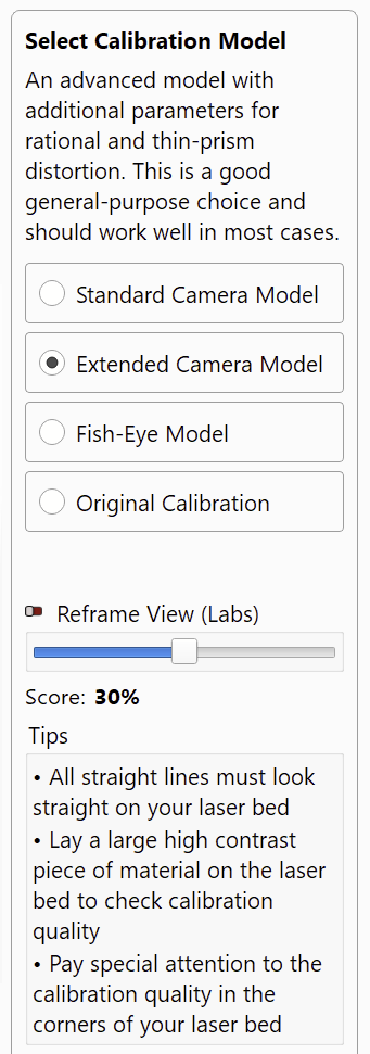
I haven’t tested the “Refine Corners (Labs Feature)” from the previous step when capturing the pictures. That sounds worth a try if the corner inaccuracies remain. (Or disable the feature, if it was already active)
I asked about the “Refine Corners” option:
This feature can be useful when extreme fisheye lenses have such a high distortion in the corners, that the tags appear rounded and therefore can’t be detected.
Refine Corners lowers the threshold to also recognize slightly bulged AprilTags.
It’s not needed if the tags close to the edges are already being detected.
oops… and I always start over if I can’t achieve my 90%…
At least I won’t recommend it in the future, as I have done diligently, but always with the understanding that this is the way I do it 
thanks for the clarification my friend 
What is the differ : Extended and fisheye ?
I got a better understanding of the Score % value now:
The score is based on the average error between the detected calibration points and where the camera model predicts they should be. It isn’t a direct indicator of calibration quality.
A calibration that only covers the center of the image often scores higher because the center has very little distortion. Once you include the edges, the model has to account for the real-world imperfections, so the score naturally drops, even though the calibration itself is more accurate.
From the notes in the wizard:
The Extended Camera Model is an advanced model with additional parameters
for rational and thin-prism distortion. This is a
good general-purpose choice and should work
It seems counterintuitive, but the Extended Model often produces better results with highly distorted camera lenses than the “Fisheye Model,” which was specifically designed for that purpose.
Back to the original problem of setting up a camera. I reached the point of auto alinement with 52 of 54 tags detected. The instructions says to click on NEXT if at least 4 tags are discovered.
PROBLEM: The NEXT button never activates, just stays greyed out, so I can’t move on!! What is going on? LB 2.1.03
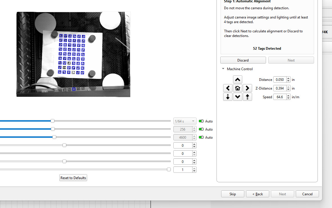
In the previous step of the Alignment wizard, It asked you to engrave the eight target markers.
It appears that this was skipped.
Your image shows the AprilTags calibration card. This is only used when calibrating the lens.
In Bernd’s first post he shows the process with the target markers.
In the Camera Alignment process that you are showing, the laser needs to engrave the eight target markers. LightBurn then detects them with the camera. This tells LightBurn where your camera is positioned relative to your machine’s work area.
I went back and redid everything and got down to the final “correct” detect 4 and I actually got 6 detected. BUT then it went to a screen that said, does the WARPED image look correct. Well, it certainly looked “WARPED” so I said ok. Now everything in the window remains WARPED and if I try to put circle in the design, it doesn’t look right.
I give up. I’ll just throw the camera back into the box and forget it and use “USER ORIGIN”, which works well for placement.
Thanks for trying, but this is just to much to try to accomplish just to get something set up.
Here is the calibration on my laser..
My biggest concern, from day one with calibration on this larger bed is the ability to get good engravings on all 4 corners..
as we all know the right front corner is the weak power quadrant, and it impacts being able to hone in on the cross hair center with the camera…
I understand on most machines this is not an issue since the beds are smaller.
but with LB being the Premier tool for most, I had asked before that the user be able to select each quad for LINE/ENGRAVE individually and then have access to speed and power to get the best targets on all four quads…
not sure how to handle this other than run the process twice and put extra sheets over 1 and 4 (left side) and then only the 2 and 3 targets will get cut/engraved a second time… yuk…
Comments please (HOPING THE LB FOLKS SEE THIS )
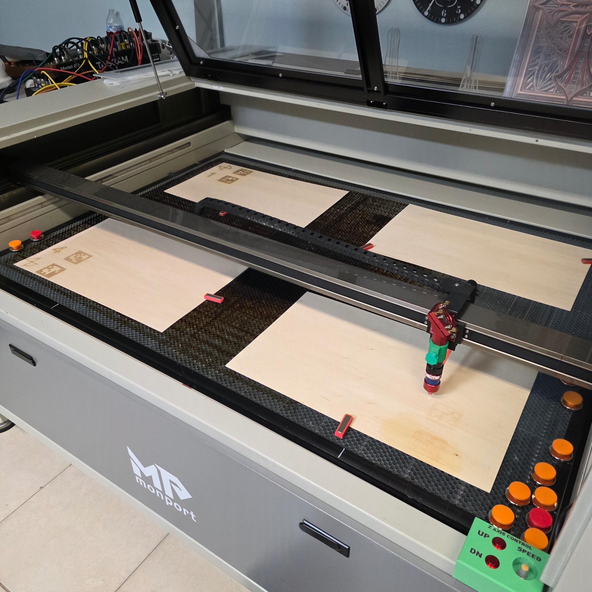
I will try to calibrate the camera so that it covers the entire work bed as best as possible. Then I will run a deviation test, with representative measurements.
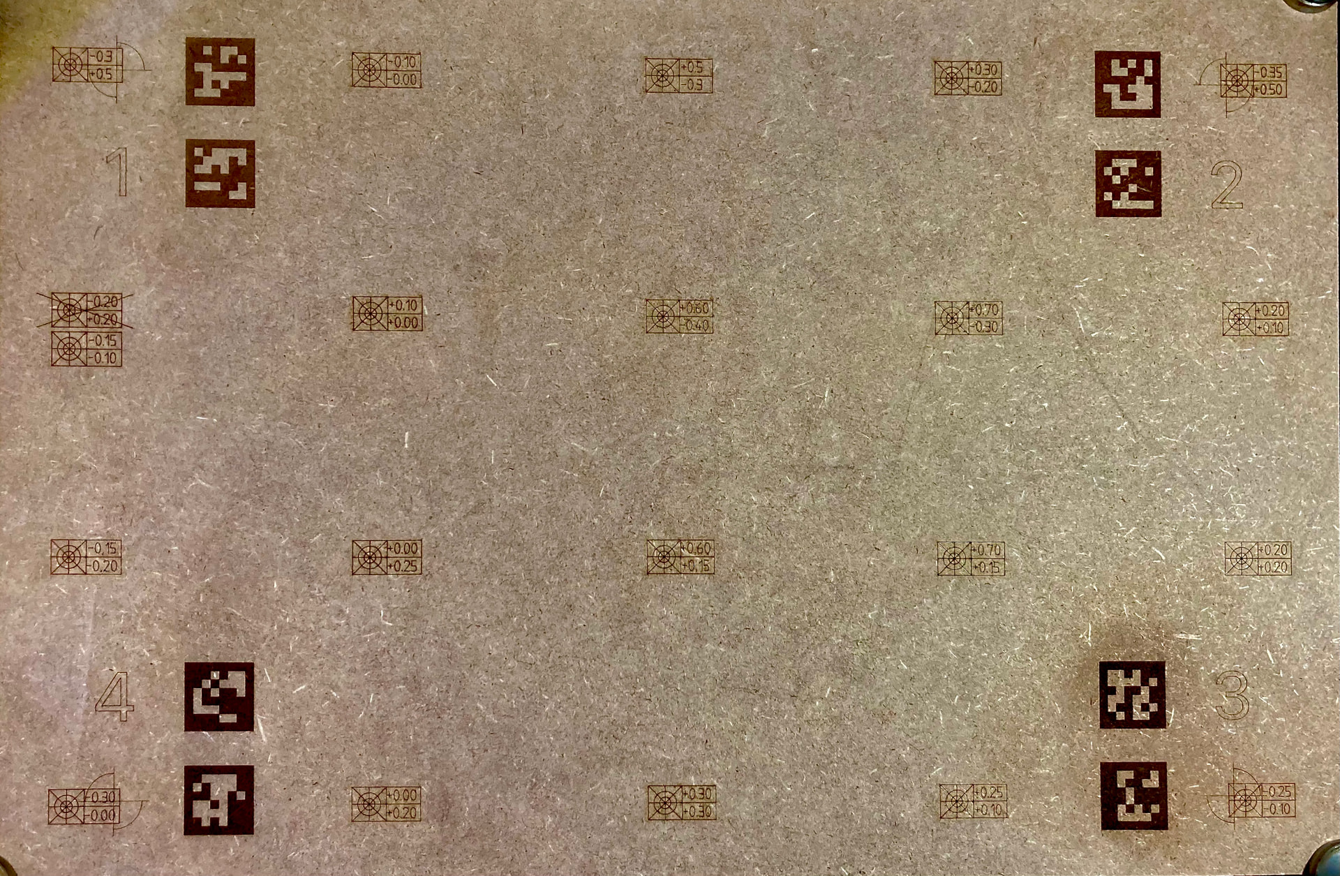
It’s an older test that shows my deviation at different positions of my 600x400mm workbed.
Measurements are done in this way, that I engrave my target mark, afterwards adjust the deviation of X and Y and engrave the found deviations into the box. Then I set the compensation to 0 again to start the next field.
With larger work areas, you have to be extra careful about unevenness of the work surface. The large plates can easily bend a couple of mm above the diagonal, with the result that the camera alignment no longer fits the entire area. This is not theory but proven practice.
The problem with a certain area that is more inaccurate than the rest, can also be caused by the camera mounting. In my case I had to change the mounting angle of my camera in the X direction by about 1mm, which gave me a better average value. I generally spent a lot of time finding the best possible positioning, even though the software can/should compensate for it. My philosophy is, anything that can be optimized mechanically does not need to be compensated for with software.
Once you have found the deviations for the entire bed, you can fine-tune separate areas, the middle for example, instead of finding an average value which is coarser because it has to compensate/cover the entire area.
For very precise work I do a quick check in the segment I want to work on and fine-tune the X and Y deviations.
What does a camera image of your work area look like?
Have you been able to achieve better exposure results with manual adjustment? I often work with very dark images because they just give me the best results, i.e. I can better see what is happening.
Agree… I have the bed pretty level , all four corners and center are +/- 0.5mm
luckily the bed is easy to level…
I am still trying to find the best camera to cover the bed, may have to settle on a smaller center area but I have had a good set up and may go back to my 8mp camera…
Tomorrow I plan on spending time on the camera setup, 3D print some proper camera holders etc. today I fixed all three hindges and the lid now opens and closes evenly with little effort,
the 110lb gas struts put so much side pressure that opening and closing would twist the hinge, now that that issue with the 80lb struts is remedied… I can move forward…
Will take pics and post more ‘progress’ I hope
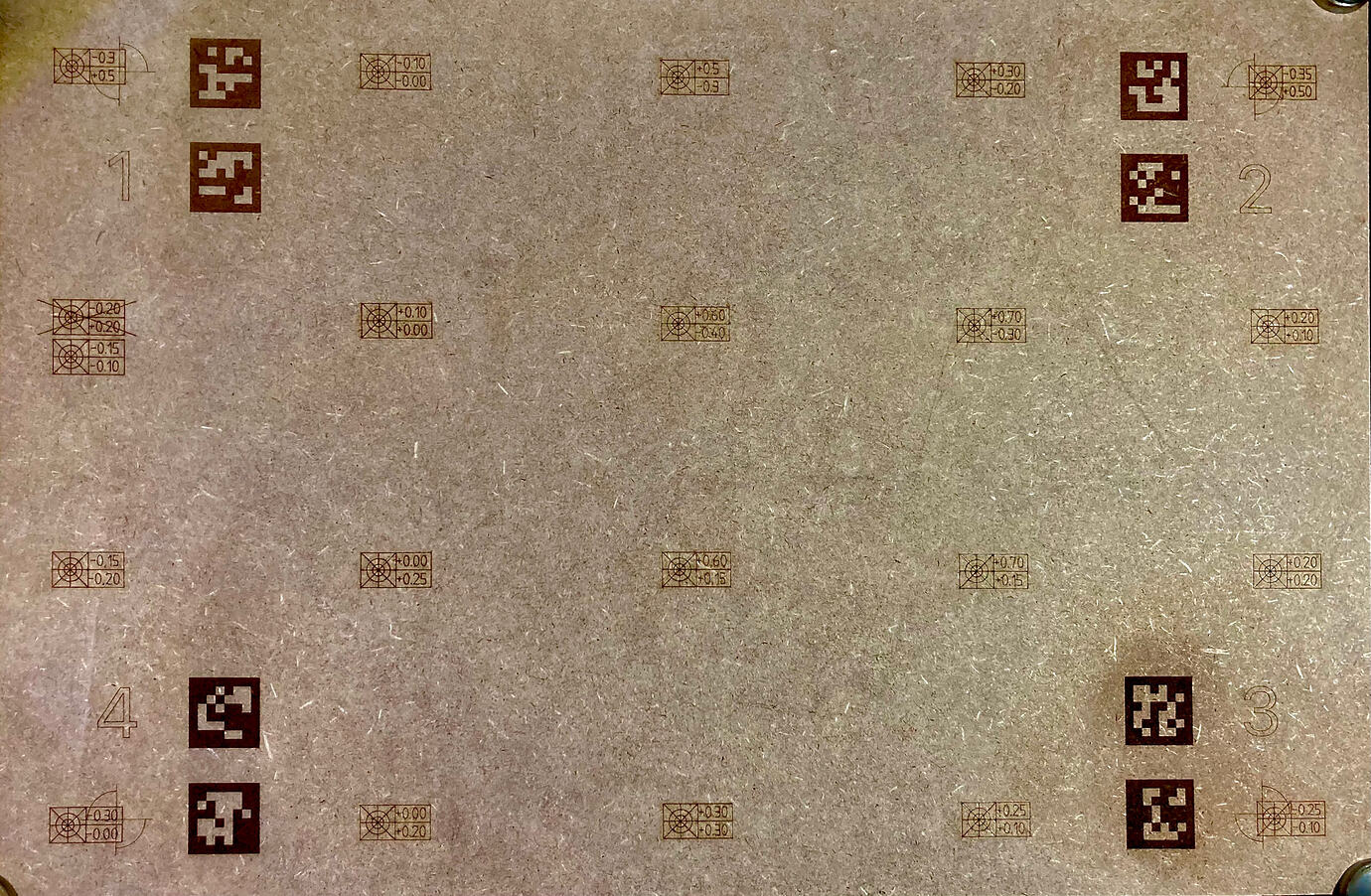
That sounds good, I’m reasonably sure that your workspace, even though it’s large, can and should also work with the right camera. According to LB’s own calculations there is no problem - if the mounting height can be achieved. If you have 900mm mounting height a 90-95 degree lens should be able to show it all. What about your 100 degree 16 mp camera, have you tested it?, if it can’t capture it all in super quality I don’t understand the world anymore
That should be fine.
Often we don’t notice that the plates bend a little, I once spent (too) much time fine-tuning my center until I noticed that the spacer in the middle under my honeycomb (2mm) was missing!!..
By the way, it can be easily tested, fine-tuning the camera deviation and then changing the focus by 2mm, people will be surprised.
Yes, that plate is exactly 600x400mm, MDF and I think I engraved calibration marks in 2 passes because it wasn’t dark enough. I will look into the parameters and report back later.
The thin lines/text are engraved with 100mm/s 15% max and 8.5 min power.
If you’ve engraved the four markers including the Autoalignment tags, but the camera can’t detect them, you currently have these options:
- Change the lighting on the bed
- Change the camera’s exposure, or brightness (If supported by the camera)
Or you can go back four steps in the wizard and switch to “Manual Alignment”. If the target markers were not moved, you can then zoom in to manually select the crosshairs.
Is the laser power so uneven across the four corners? I hate to say it, but the mirrors might need to be adjusted.