Testing the camera setup in version 2.1.03

Well got the full bed set up with the 100Deg camera…

Managed to use the LB PREVIEW mode to move the laser to the QUAD needed and
burn the patterns a few times to get them dark…

But after all that and setting up the offsets…it worked ok
EXCEPT ! the dang camera has auto-that seems to have a mind of it’s own completely throws
the sizing off each time the gantry moves under the camera view…
Cripes so close…

I need a manual focus camera that has a 90Deg FOV 16mp seems to be ok…
The 100Deg camera I am using is just a bit to far focused and the 76Deg is too close…
so I believe a 90Deg will be fine…

And yes I turned off the AUTO-FOCUS no-joy… the camera still wants to do its thing…

I’ll look for a 90D if it exists…with no auto-focus…
What a shame was able to get all the April Tags to light up and the alignment across a 1100mm was about 1mm..
I can live with that, if the auto-focus would play nice…but LB updating throws me a curve ball and the camera
looks like sailors eyes after a three day shore leave…

More to come I guess…
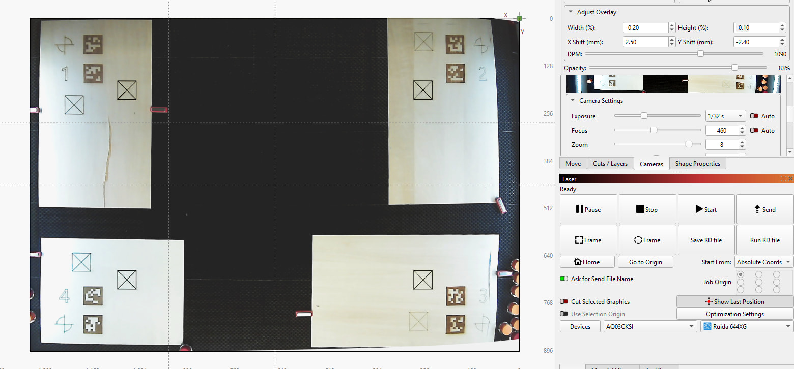
The X- and Y Shift under “Adjust Overlay” should not be needed if everything is correct.

Which exact camera are you using?
It’s known that Auto focus cameras can be problematic. The main problem is that with the lens correction, we can correct.. ..the lens. The problem with autofocus is that the lens and its distortion are constantly changing.

I haven’t seen a camera yet where you can turn the autofocus on and off.
Just thinking out loud—theoretically, we could use a drop of superglue to permanently lock the autofocus mechanism in place so the focus doesn’t keep shifting.

A note on the camera resolution and maximum possible placement accuracy:

The Monport 130 has a working area of 1295 × 889 mm.
When using an 8 Megapixel camera, (Roughly 4000 x 2000 pixels) you get a maximum resolution of around 0.4mm per pixel.
After accounting for lens distortion and perspective correction, a realistic result would be ±0.5 to ±1 mm of placement accuracy. Possibly more on the edges, because the lens distortion stretches the available pixels further.

That’s precise enough to place designs on material scraps, but if you need greater precision across the entire bed, you should either use a higher resolution or use two cameras at the same time. LightBurn can stitch the two images together and merge them.


Using a head mounted camera is another option. This can be very precise, but scanning the entire workarea takes a long time.

Can you explain what you are aiming to achieve, and how you would like to use the camera features?

This idea is in my To-do list but its related and thought I will ask if we can “split” the stream from one camera in half so that each half has its respective alignment and increase accuracy?

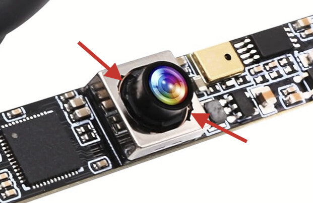
ELP 16MP Autofocus USB Camera with Microphone for Computer Mini UVC USB2.0 Lightburn Camera Micro USB Security PC Camera Module Laser Engraver Webcam Board (100degree No Distortion Lens)

Got it on amazon…

And yup autofocus is problematic…tried a few times to calibrate…it was pretty good over the large bed

but as soon as autofocus decided to ‘think’ the scaling when south…

I ordered a Fixed focus camera…

ELP 16 Megapixel USB Camera Module with 75degree

I’ll make a 3D holder and get it mounted :slight_smile: it’s all good fun and such…
I dont need precision, I just like to drop a scrap and cut parts, but at least +/-2mm would be really nice…

I have the Yongli red Dot on my last tube so the RED DOT thru the tube gives really good alignment …
when I need to find corners etc…

Check if you can disable it with RaspberryPi…
Or Where can I turn off autofocus for my Lifecam Cinema camera? - Microsoft Q&A

Good to hear that you got a fixed-focus one ready soon. I’ve heard good things about the ELP brand in general.

To be honest, I haven’t seen the “Auto” toggle for the focus on any camera I’ve used.
It would be interesting to find out if some other program can properly keep it in manual focus, or if the camera itself is automatically reverting to autofocus.

If it can’t be used for anything else: Once it’s focused at the correct distance, I’d still consider fixing the focus lens in place by applying a small drop of superglue here

I’m not sure I understand the question. Did you mean “Combine the stream from two cameras into one”?

Then, the answer is yes.
Both camera lenses need to be calibrated separately.
Then in the Alignment wizard, choose “Two Zones”

Repeat the alignment for the right camera and select “Two Zones - Right Half”

“Update Overlay” will stitch both images into one.

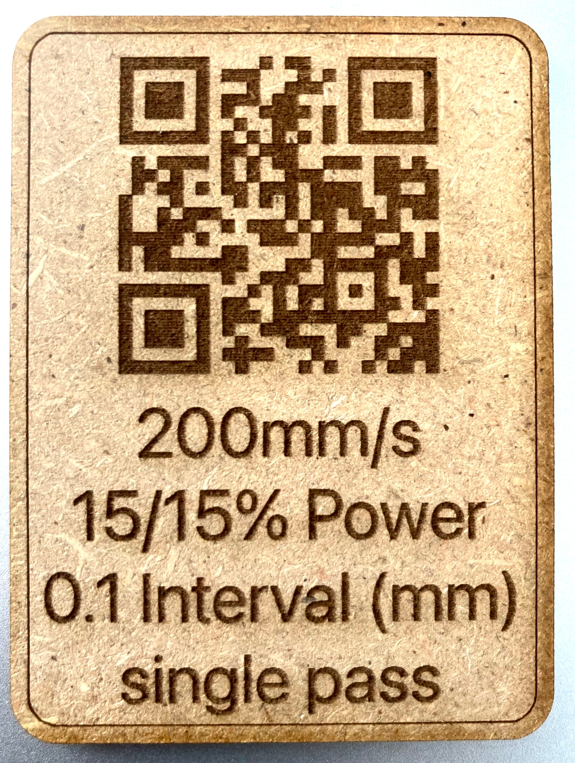
It depends a lot on the type of MDF, this one is “very dry” on the surface, where other types can be “a little greasy”. The last of the two cannot (I) get engraved that dark.

But here are the settings from the darker one.

Ever since this option has been available, I’ve been thinking about trying to trick LightBurn into thinking there are two cameras when in reality there’s only one. So the question is can we “split” the stream of only one camera in two? each part with his own alignment?

I don’t yet see how this could increase the accuracy.

The lens of the camera is being calibrated with many points over the entire field of view using the April Tags. (Unlike the 9-Point calibration which can cause inaccuracies with Galvo lenses that have non-linear distortion, If you are familiar with this situation)

What you’re suggesting would be similar to using more than four target markers during the Alingment in a single camera image. Is this correct?

The result could be different…
Have to test when I got some time.

To get more accuracy typically you would want to increase the resolution or reduce lens distortion that needs to be corrected.

Splitting the feed in half effectively makes both of these things worse. I’m not sure how that would help.

We have two machines in house that are 1600 x 900, and we don’t have this issue.

We had a 1200 x 600 machine that did have power drop in the front corner, but that was resolved by doing proper beam alignment. I suspect your issue is also alignment, not power loss - a laser shouldn’t be diverging that much over 2 meters.

Check to see if any of your mirrors or lens tube get warm when engraving for any length of time in that front corner.

I suspect what he means is that he wants to have a different alignment matrix stored for the left half and right half of the lens - More like a grid of points instead of just tagging the 4 corners.

It’s feasible, but the current system doesn’t support this.

I am sure you will hate to hear this but your laser is absolutely not aligned well enough. I have a 1400x900 Omtech that I have had to spend a LOT of time working on the alignment with, but it gives me consistent power across the bed now.

Key things to note-

  • You need to have your beam hitting the center of your lens and hitting it perpendicular, being off at an angle will cause power loss and make the output wander
  • Just because you are “center” on the mirrors or the input at the focus head does not mean that will get you centered on the lens and square.
  • That machine probably twists based on the leveling feet. Just because your nozzle is tram to the bed, does not mean your machine is level and square. One of the big things I fought was my Y rails were twisted due to my leveling feet not being correct.

I wish you luck, getting a well aligned laser is a journey. I ended up using the reverse alignment laser from American photonics. I just use it to get my lens, mirror3 and the path between 3 and 2 all square.

Hi Chuck,

If the alignment is accurate around the tags, but not anywhere else, it is almost certainly a lens calibration error. I would repeat the lens calibration, holding the target up close to the lens. Try get a lot of captures, covering all areas of the camera frame.

You can see in the image bellow that lines are not perfectly straight, this is also a clear signal that the lens calibration is off.

Thanks for taking the time with all this feedback! This helps us improve the UI for the next version.

I have missed this part earlier.
Is this the one you have?
As @JoeSpanier mentioned, having a visible beam indicator is a huge help when calibrating the mirrors.

Did this come pre-installed in the Monport Effi, or did you add it yourself?


When using this, it’s of course important that the tube’s beam and red dot are perfectly in line. The link above explains how to do this using the set screws.

When you jog the head to every corner and fire the co2 laser, does the red dot from the combiner perfectly align with the burn marks?

Yes but the Red model, a little harder to align but I have it just about perfect with my 3" lens

I have the Monport 130W, not the effi model and I added the red dot myself.
Also mentioned I added a 100ohm Pot ont eh power wires

and I’m pretty sure I have the laser ‘LEVEL’, about two months ago spent 3 hrs leveling :slight_smile: (as we do)
all four corners (on the X / Y gantrys ) made sure the front and backs were level.
I know the Frame could be off so the guide rails are the only way to ensure the tube travels level across
the entire bed… and then I made sure all four corners of the Bed were level to the Laser tube,
like I said 3 hrs…
I also have the the Red DOT centered on all 4 corners, travel left to right, the dot is centered,
Also checked the alignment with the AmericanPhotonics Reverse laser pointer, these are really handy.

I’ll go back thru the alignment as suggested as time allows…

**
********************************
********************************
Did a few tests …**

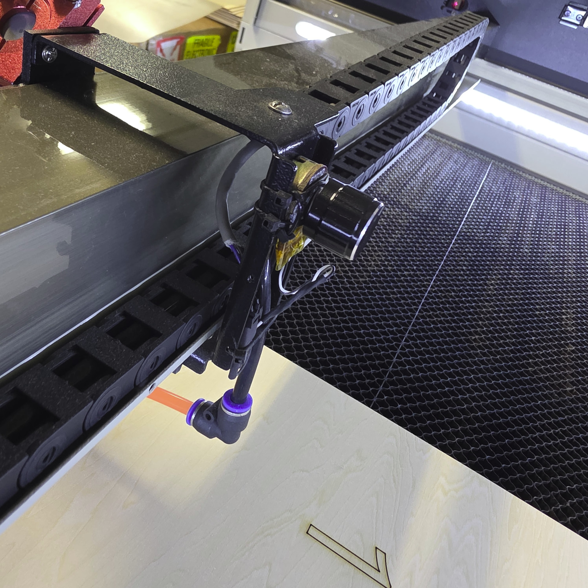
Back side of gantry with installed intensity POT for the LED Pointer

ADJUSTED TO FULL BRIGHTNESS

ADJUSTED TO MINIMUM BRIGHTNESS

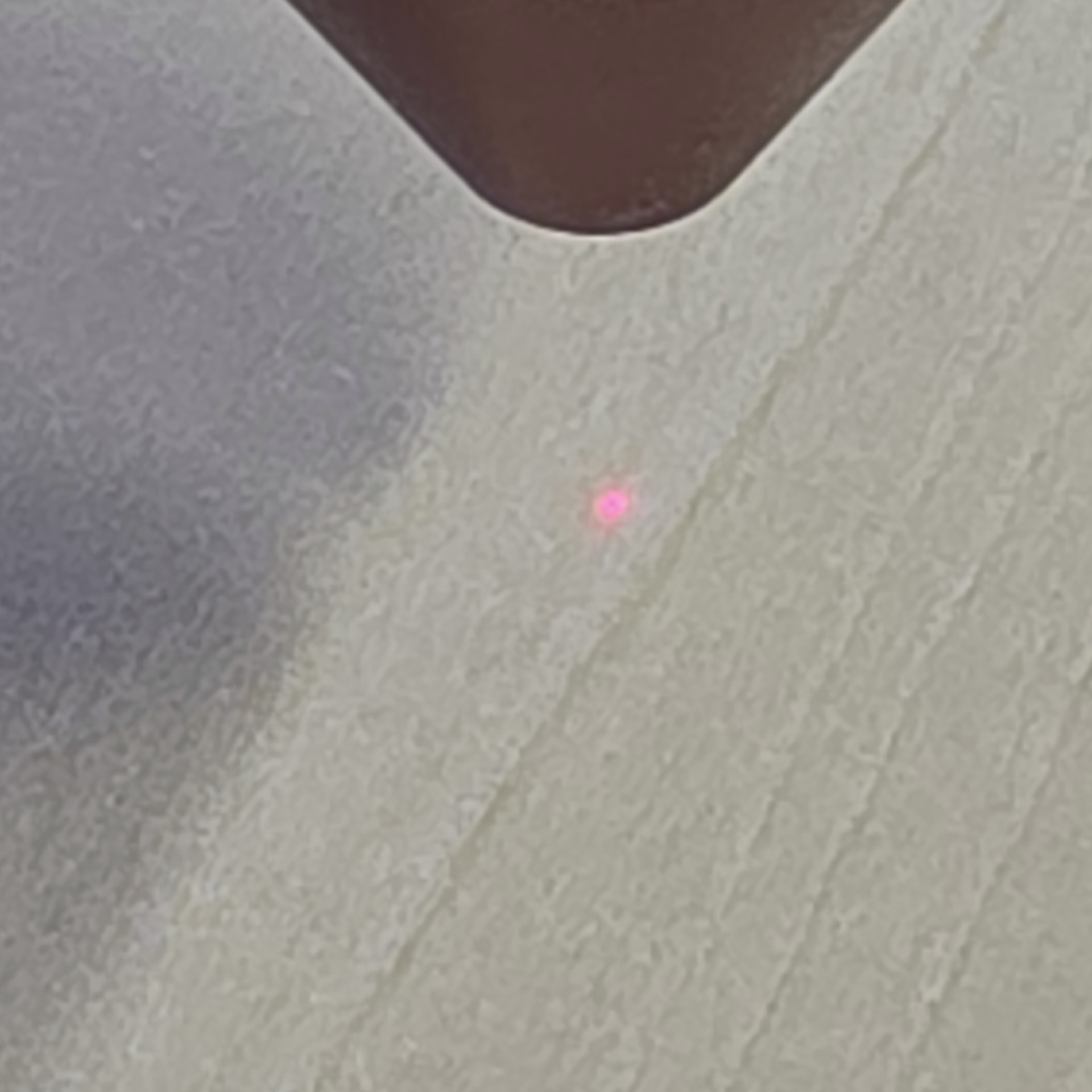
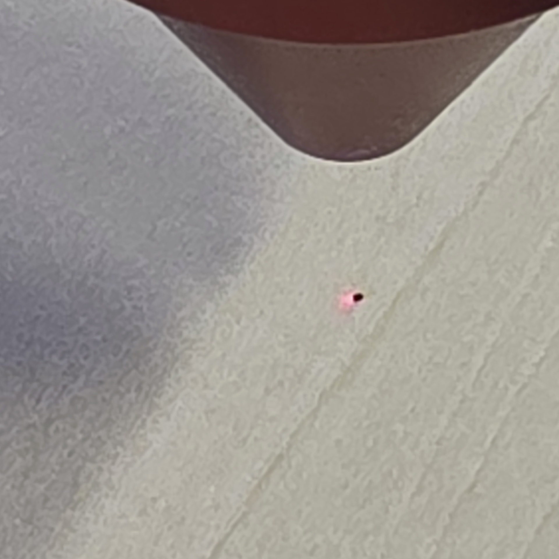
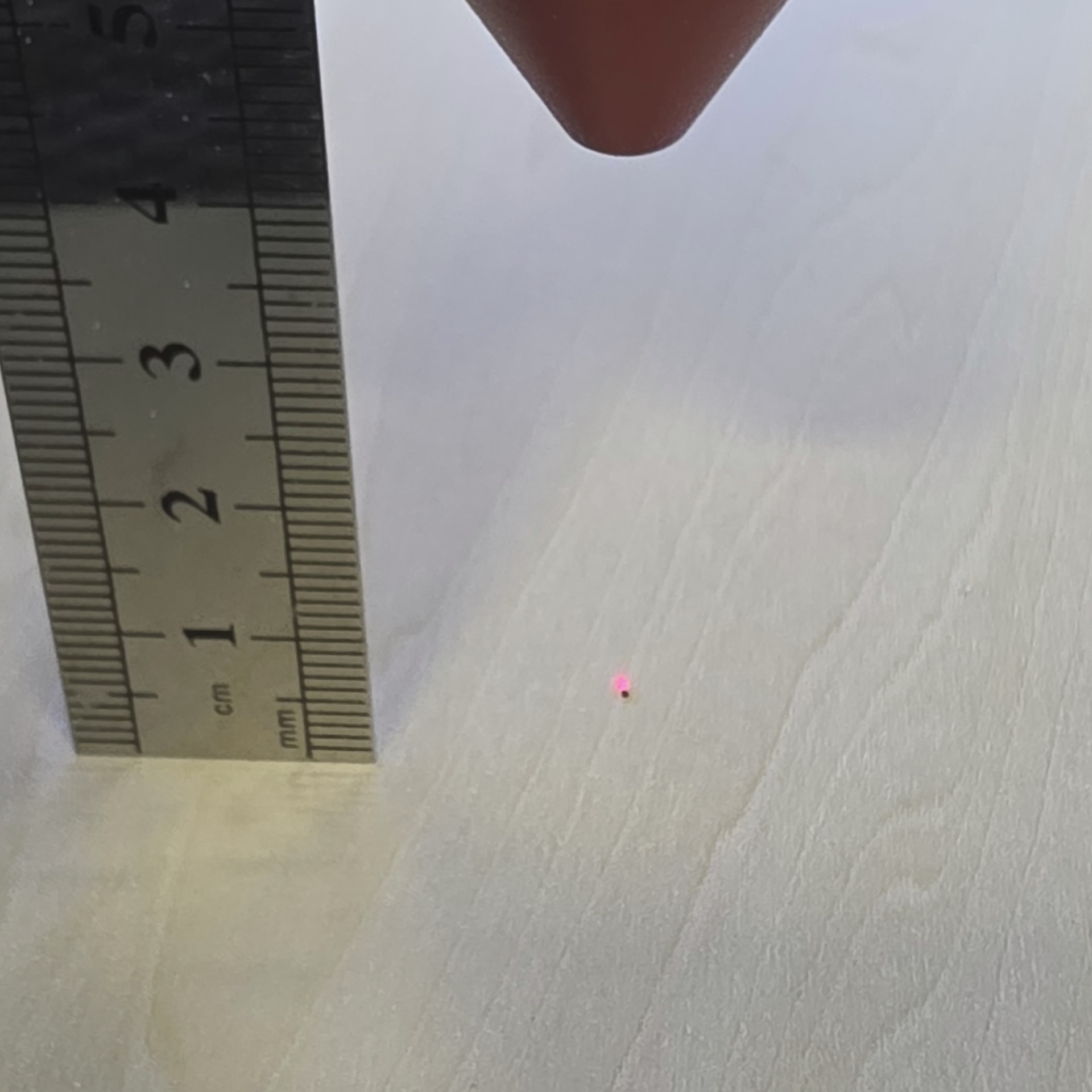
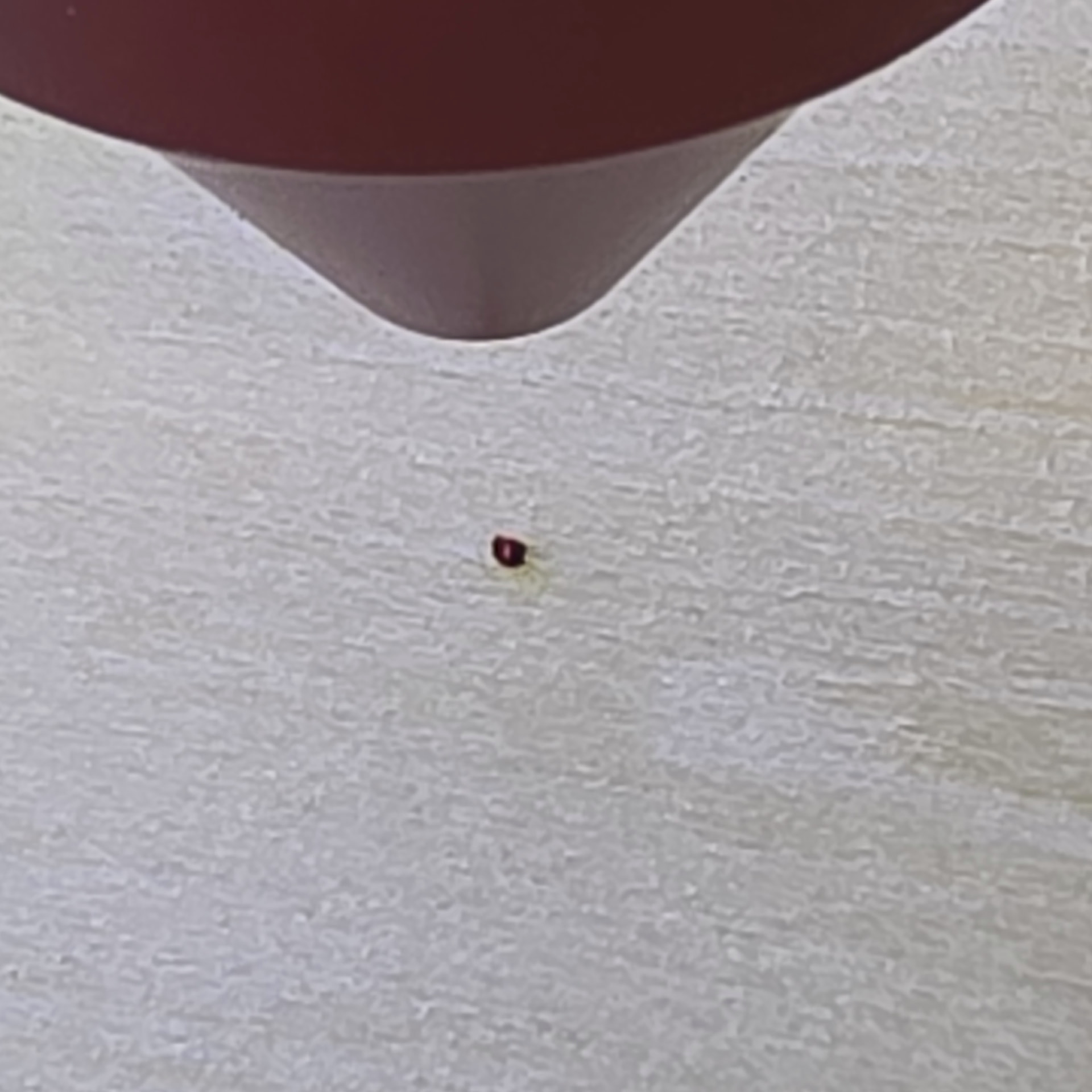
PULSE DOT 10ms 15%pwr

(TAKEN AT THE RIGHT FRONT OF THE BED )

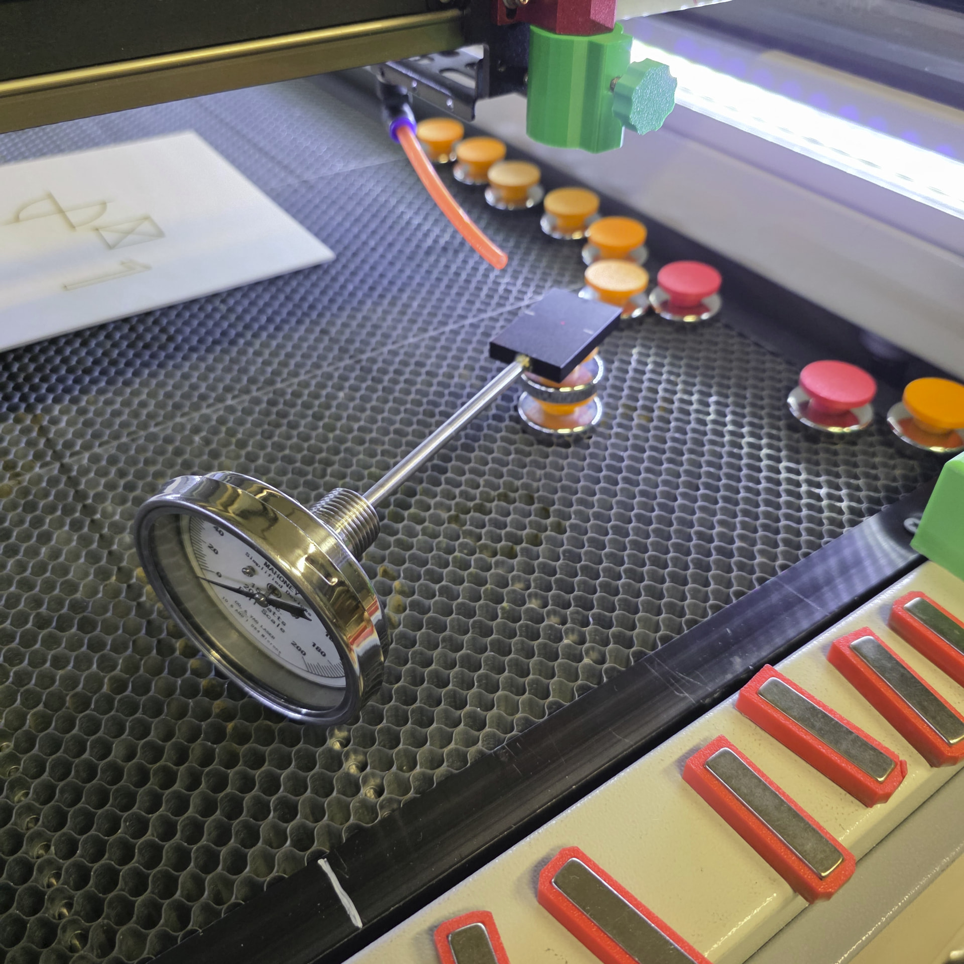
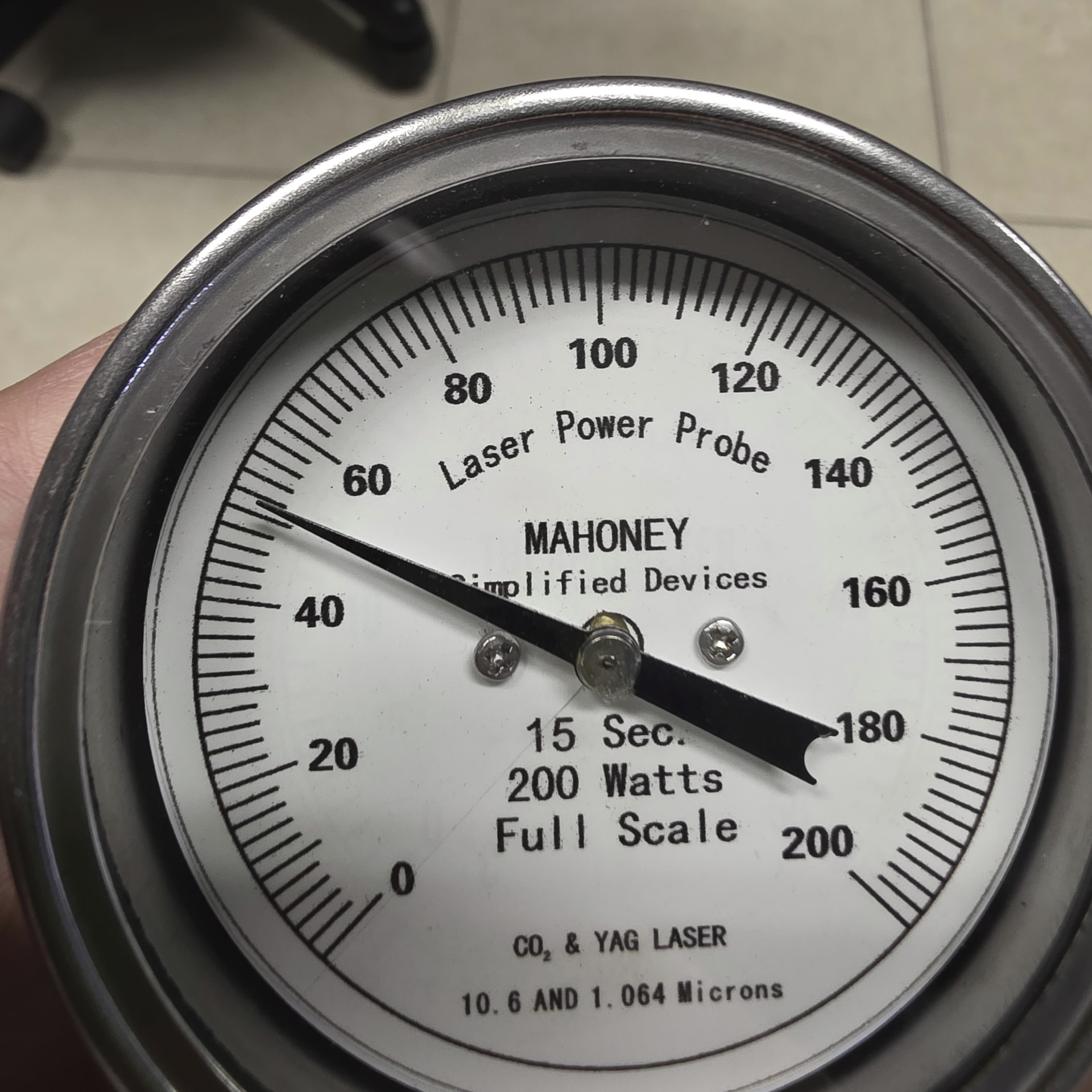
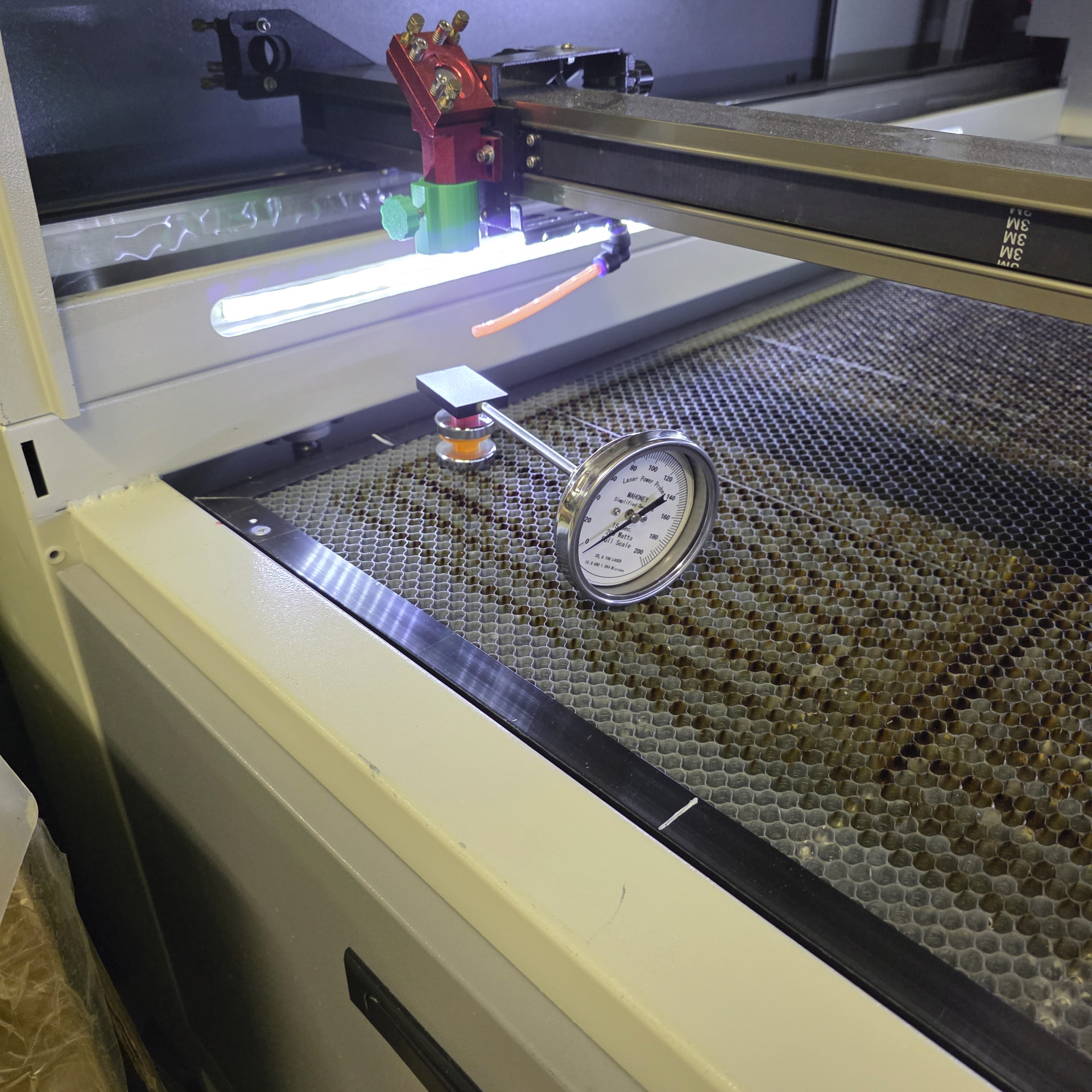
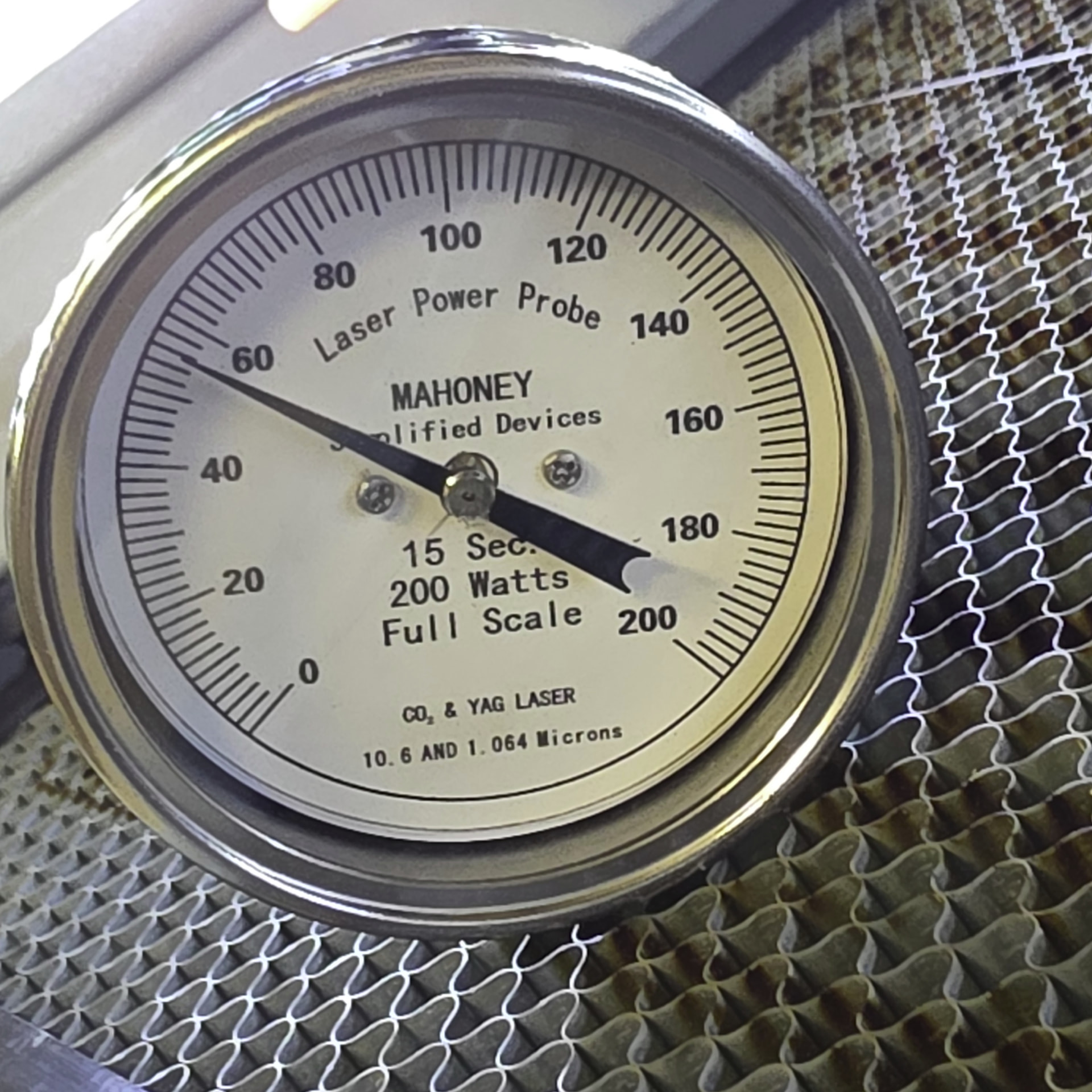
Did a couple power tests also…
RIGHT FRONT 50% POWER

52W

LEFT FRONT OF BED

56W

At 10ms 15% power this is a pulsed dot… 3" lens 11mm height FP

Bed Lowered to 45cm dot still pretty good so vertical seems ok…

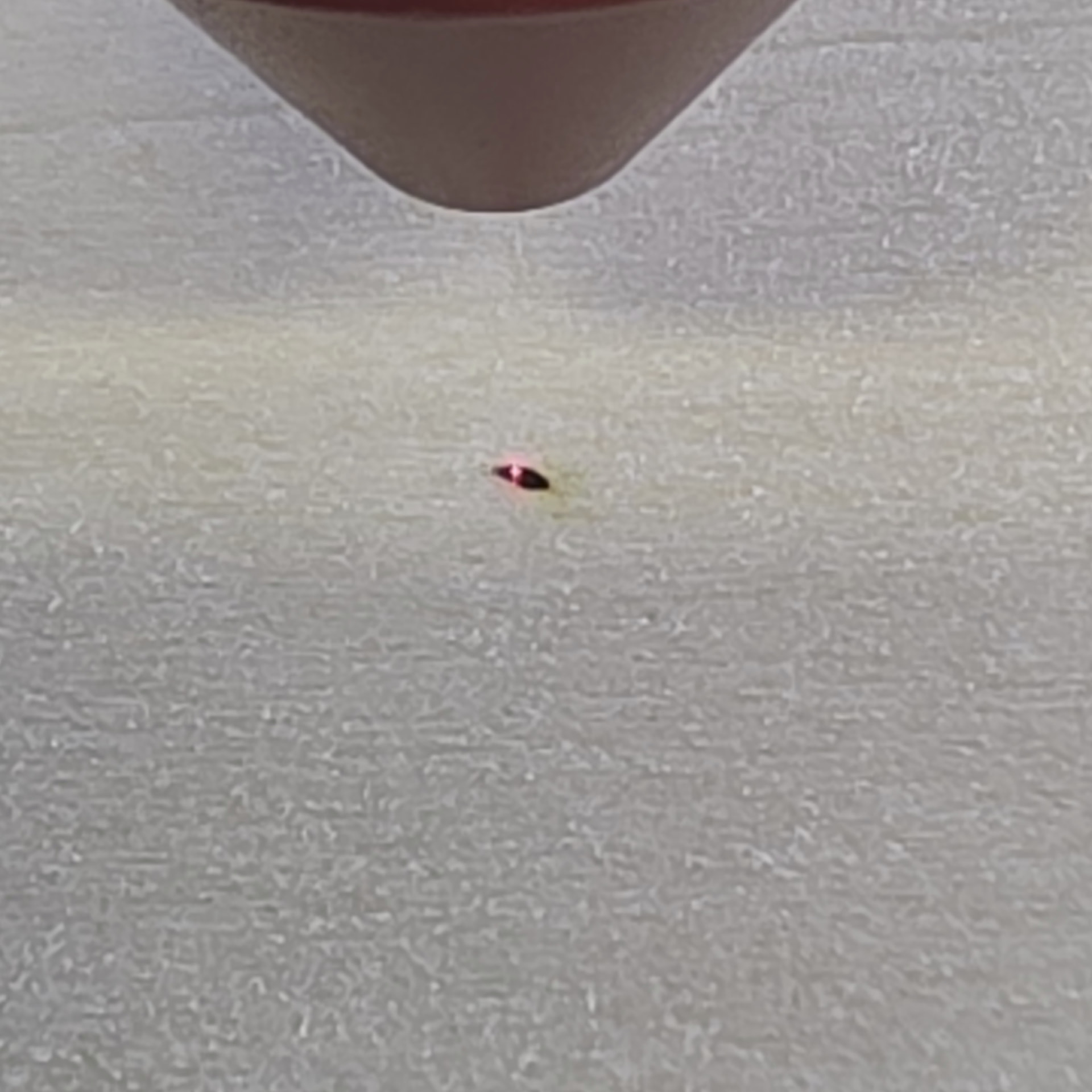
Another thing I noticed… for all the lens experts to chime in on !

At 10ms 15% power this is a pulsed dot… 3" lens 11mm height FP

At 10ms 50% power this is a pulsed dot… 3" lens 11mm height FP

it seems to be elongated…

that’s all folks

Seems we have gone through similar journeys. That elongation you are seeing is likely the beam hitting the side of the cone on the way out, so there might be more tuning to do.

You are seeing it at 50% because the reflected light is getting enough power to make a burn finally.