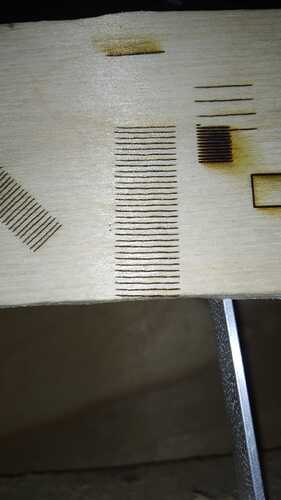
Hello, please help me solve the problem. There is a Laser engraver: Frame with NEMA17 stepper motors, 10 W solid-state TTL laser, control board - Makerbase MKS DLC32 V2.1. I work in the LightBurn program. And here’s the catch - when I started working, I calibrated the burning sizes along the X and Y axis by burning squares with the Line function with certain sizes and adjusting the coefficients. The dimensions specified in the program completely coincided with the actual dimensions of the burning. So far so good. And then I wanted to “fill” the same square using the Fill function. And this is where the problems began. I set the burning interval to 0.1 mm, but in fact the engraver started burning at intervals of 1 mm. Question: what am I doing wrong? maybe there are some separate calibration settings for Fill and Line? Because when I reduce the coefficient by 10 times in calibrating the Y axis, it is burned using the Fill function to the exact size. But then, using the Line function along the Y axis, the dimensions become 10 times smaller.
Exactly what does this “coefficients” mean? What are you adjusting?
If you create a rectangle and burn a Line box, then switch to a Fill and repeat the run, Lightburn will exactly fill that box (subject to mechanical repeatability).
Coefficients of correspondence between the engine rotation angle and the distance on the plane.
Linear dimensions are accurate, but the line spacing when filling is 10 times larger (1 mm instead of 0.1 mm)
I appreciate your math education, but this makes it difficult for some to understand. Lightburn is a tool pathing software, so it is better to relate in those terms.
Upload your .lbrn2 file so we can see what you are trying to accomplish, and what results you are getting. On Fill, line spacing is a simple text box entry using either DPI or interval. Your description leads me to believe you enter a 0.1mm interval and you get 1mm line spacing in the output. Unless you have an unauthorized copy of Lightburn, I seriously doubt this is what happening.
Again, upload the Lightburn file with the problem and we will go from there.
10x10.lbrn2 (2,8 КБ)
I’m sorry)
The file is simple. I’m attaching it. I also attach a photo of the result. Width - 10 mm. the distance between horizontal lines is 1 mm.
With LightBurn up and running, with this project in place, click File, then click Save GCode and attach that file into a reply.
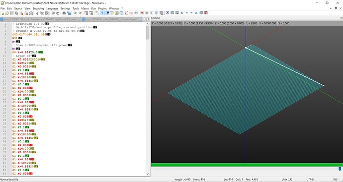
I looked at your program with the GCode exported from LightBurn and it appears to be a filled square as predicted.
I use a plugin on Notepad++ called NCNetic to view GCode files.
The output looks perfectly fine. and the interval appears correct.
I am optimistic that your GCode will show the expanded fill and hopefully offer some clues as to why it’s happening.
10x10G.gc (4,5 КБ)
I have a guess. Could it be that I loaded the firmware into the board not for the laser, but for the milling cutter, and therefore it does not need to take a step of less than one millimeter, since this is more than enough for the milling cutter?
You can also use ncviewer.com
As for the above issue, it sounds like you may have adjusted your axis calibration incorrectly. Can you enter ‘$$’ and ‘$i’ into the Console tab, and copy and paste the text from the console into your reply here?
I didnt know this existed! Wonders if theres something similar to sublime text!
Possibly, but your GCode shows a square as intended.
These commands request a couple of reports from the controller. $$ will show Machine Settings and $i is an ‘information’ report that will usually have the machine name, GRBL version and the build date. ![]()
Sometimes it crashes.
Guys, I think I have overcome this problem, although I don’t believe it myself yet).
I started checking the settings configuration ($$), and saw the value $1=250. I changed it to 25 and everything worked. The square is correct).
I have no idea how exactly this value is related to my problem, because I am sure that I have already rechecked all these values and changed them to standard ones. I’ll test it for a couple of days and see if everything works as it should. Perhaps flashing the board helped.
Just in case, I’m posting my settings.
$$
$0=10
$1=25
$2=0
$3=5
$4=0
$5=1
$6=0
$10=1
$11=0.010
$12=0.002
$13=0
$20=0
$21=1
$22=1
$23=5
$24=300.000
$25=1000.000
$26=250.000
$27=1.000
$28=1000.000
$30=1000.000
$31=0.000
$32=0
$38=1
$40=1
$100=160.000
$101=160.000
$102=800.000
$103=100.000
$104=100.000
$105=100.000
$110=5000.000
$111=5000.000
$112=6000.000
$113=1000.000
$114=1000.000
$115=1000.000
$120=500.000
$121=500.000
$122=200.000
$123=200.000
$124=200.000
$125=200.000
$130=450.000
$131=450.000
$132=50.000
$133=300.000
$134=300.000
$135=300.000
$i
[VER:1.1.2022010501:]
[OPT:MPHSW]
[MSG:Using machine:MKS DLC32]
[MSG:Mode=AP:SSDI=MKS_DLC:IP=192.168.4.1:MAC=08-F9-E0-A5-BE-79]
This topic was automatically closed 30 days after the last reply. New replies are no longer allowed.

