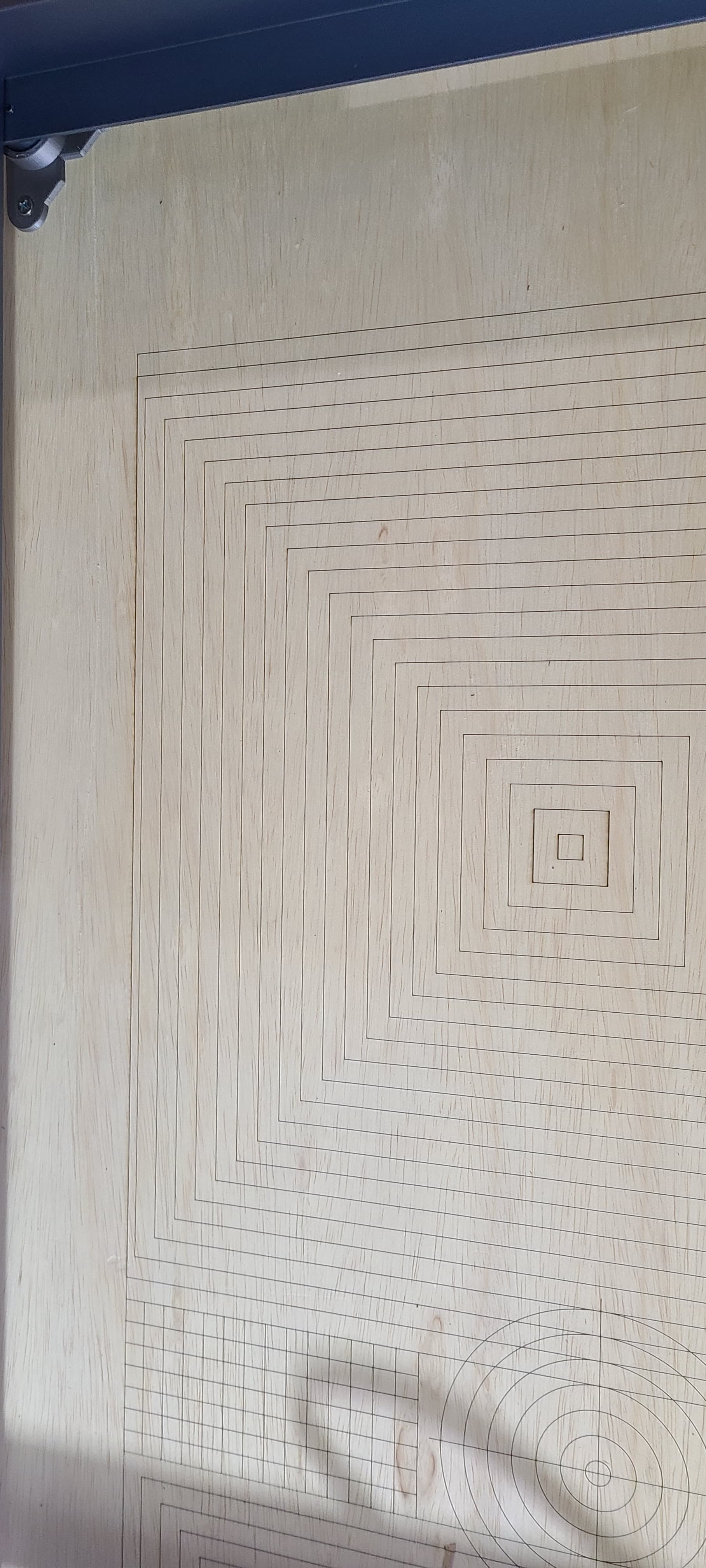
Using an X-Tool D1 10w. This is really first burn. Created my own grid in LB (430x430 on top and same on bottom with some concentric circles in center). Everything looks good in LB and it started off good burning in center of top grid and working its way out. Got about 3/4 through upper portion and i stepped out to prune a few boxwoods in the front (only a couple of minutes). Came back to check and it was working on lower portion. Problem is when i was outside, the outside two squares of the upper grid shifted on the x-axis to the right. Everything with the lower grid is aligned with these two shifted lines. Again everything looks good in LB. Any thoughts on what could cause this?
Hard to say if you didn’t witness it. You could potentially rerun the whole job at 0% power to see if you could recreate the issue.
I suspect your laser module collided with the rail at some point. If you have a pointer offset it’s likely where the offset forces a collision on the left side of the machine. This could account for why the remaining engraving is to the right.
Not sure what a pointer offset is so im assuming that isnt it. Seems like if it struck anything there would be an area in the burn that was “boogered” up. Is there a chance of a belt slippage on the gantry?
xTool machines by default all have pointer offsets and would be required if you’re using the red crosshairs. Are you using the crosshairs? Go to Edit-Device Settings and check the pointer offset setting near the top middle of the window.
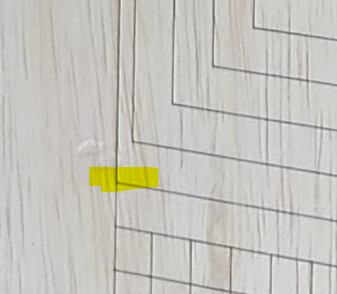
It looks like to me that the collision may have occurred in the highlighted area here or on the top of the same shape. You’re not seeing a “boogered” area as you say because the burned area simply got compressed laterally and then continued along the same vertical line as the other shape. Essentially the vertical line is doubled up at that location.
Yes. But normally you’d expect this to occur more frequently.
Hmm. Ok, i’ll check into that. Im clueless how there could have been a collision.
Oh and s crosshairs are on. Ive not changed any settings though. I utilized the framing command prior to burning and there were no issues.
Does frame use the crosshairs or does it use the blue diode laser? If it uses the crosshairs it wouldn’t simulate the collision scenario.
Have you attempted to rerun at 0% power? That would pretty much demonstrate the issue if it was indeed the issue. You could even speed it up since the path should be the same.
I’ll re run it at 0% power and see what happens and post back.
Ok. Saved my grid as a test name then deleted all entities except the outer 6 grid squares on the upper grid. When it finished the third from the last square (at the upper left corner) and tried to move up 10mm and left 10mm there was a “ratcheting” sound when it tried to move to that position and couldnt do it and just started the next square at that location. All remaining entities continued from that location. Before i turn the machine on i push the gantry all the way up and laser all the way to the left. That postion is well left of where this is occuring. My grid is 430x930. When i measure from frame of machine (left/right), the frame to grid on the left side if 54mm and frame to grid on right side is 64mm. Any thoughts on this update? Thank you for your help.
Did it reach either the top or left extreme? If not, is there something else impeding the motion? This is essentially the scenario I was envisioning but specifically with respect to left rail so want to confirm.
Remember that with the pointer offset that the machine will attempt to go farther left or up depending on the offset.
Can you take a screenshot of Edit->Device Settings? Want to confirm your particular offset. For typical xTool setups this is -16 on X. But I’ve noticed a newer module has a Y offset.
What are the dimensions of your laser module? The closest the grid could be is likely around half the width of the laser module but likely larger for various factors.
Probably wont answer all those questions based on what i just noticed. First off here is the settings photo…

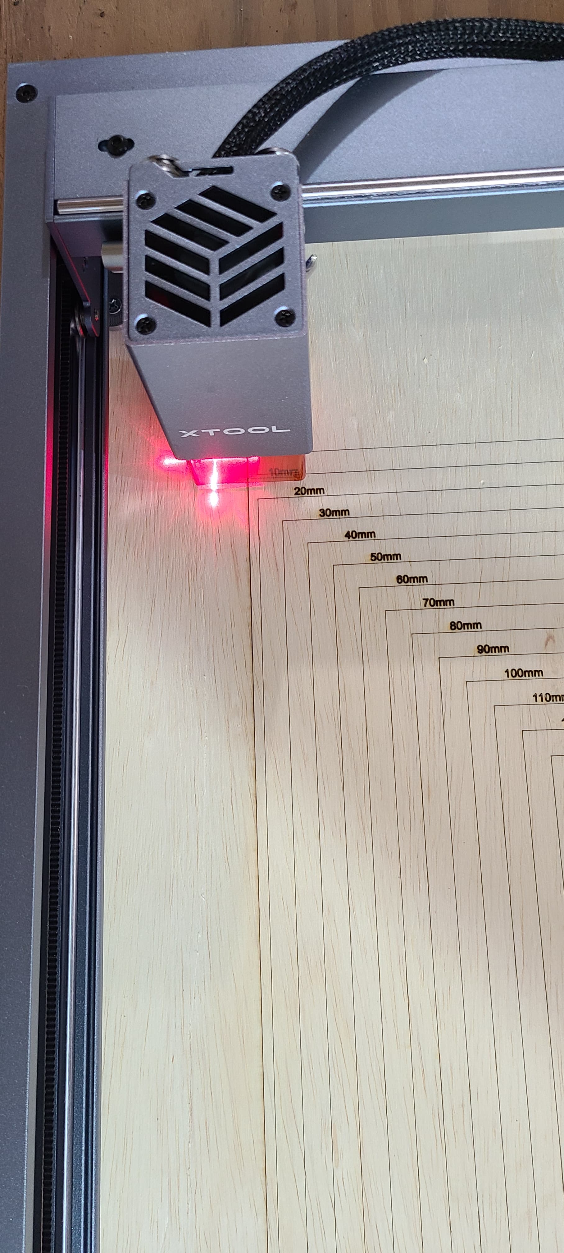
Manually moved the lasr with machine off to see if it was hitting anything and it is. Its the left side of the machine. I thought it would move farther because the red crosshairs are further from where it burns. Im also attaching a photo of that left side with laser moved to extreme left against frame.
So, its my understanding i should be able to engrave 430x930? Appears to be something with the grid as seen in lightburn and actial machine?
The part you need to be aware of to understand what’s happening is that the location of the red crosshairs is not physically at the same location as the blue diode laser that actually burns the material. The actual blue diode laser is 16 mm to the right of the crosshairs. This is why the pointer offset is enabled.
So what happens when you run the job is that the LightBurn will shift everything 16 mm to the left of where the red crosshairs are situated. Since the laser module is already at the extreme of the left side of the machine there’s no room left to shift 16mm to the left to accommodate the actual laser head to reach that portion of the grid.
So the addressable width of your laser if you use the red crosshairs is actually likely 430 minus 16mm. It’s really the right side where you’re “wasting” space since there are areas that could be burned that are never addressed by the red crosshairs.
As far as potential remedies:
- Shift your entire grid to the right by 16mm and just deal with the smaller working area. It’s also possible that xTool make the frame larger than necessary to still provide a full 430 mm but I’m not intimately familiar.
- Disable the pointer offset and red crosshairs and use the blue diode laser for framing and all other operations.
I gotcha. Thank you for your input. I really feel ill end up using the grid lines and the frame command to line things up. I dont plan on using the entire surface for a burn (although you never know what the future holds). So if i wanted to flip this over and burn another grid i should probably make it 410 mm wide and it should work fine. Is thst correct?
It’s not only the size that matters but more the position. Make sure you’re shifting the design to the right by at least 16mm.
1 Like