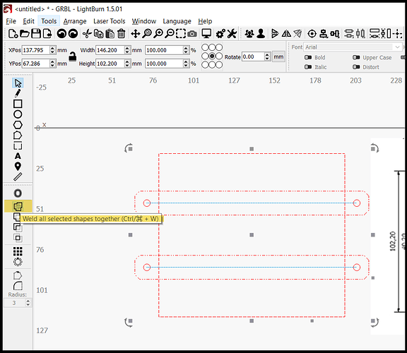
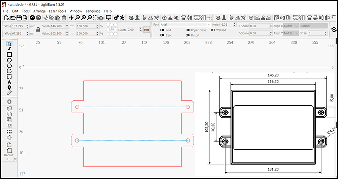
Hi
I traced the outline of a template I am trying to make. Unfortunately its very untidy the tags are all jaggered and uneven I would like to know how to tidy them up also i need the drill holes in the centr of the tags. I dont know how to just select the tags.
GSMc Outline.lbrn2 (13.0 KB)
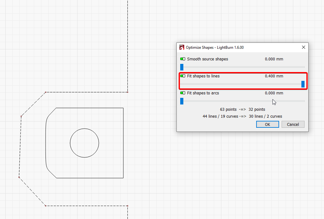
You will need to do a little work, but you could start with
Select shape
Edit → Optimize shape
However, as you see the lines are not perfect then
Might be better to try to optimize better the trace
Can you post your original image?
Hi Thank you for the advice. Still have lots to learn here is the original Image
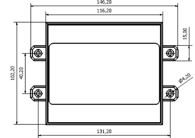
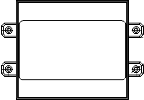
image
Exactly what I was about to suggest, followed by a little node editing.
How do I do Node editing. I am assuming I can re draw the nodes so they tidy and fit
You’ll find the “Edit Node” tool here:
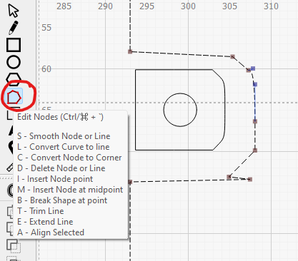
You’ll find documentation on the tool here:
I have now tidy up the shape the tab but I want to delete a line the instructions say however over the line and press D. However When I do that the whole shape is deleted
GSMc Outline.lbrn2 (9.9 KB)
I have re drawn it probably a long winded way but not sure how else to do it.
Now I am trying to work out how to delete the lines between the tab and box
You may have to click the line segment or node you want to delete.
I didn’t have any issues deleting lines or nodes myself. It might be worth practising a bit and maybe watching the video that’s on the documentation page I linked to a few times just to get the hang of it…
GSMc Outline.lbrn2 (9.2 KB)
I just could not get the nodes to delete I watched the video followed instructions and failed. So no doubt some practice is needed. I did However win by using the boolen features
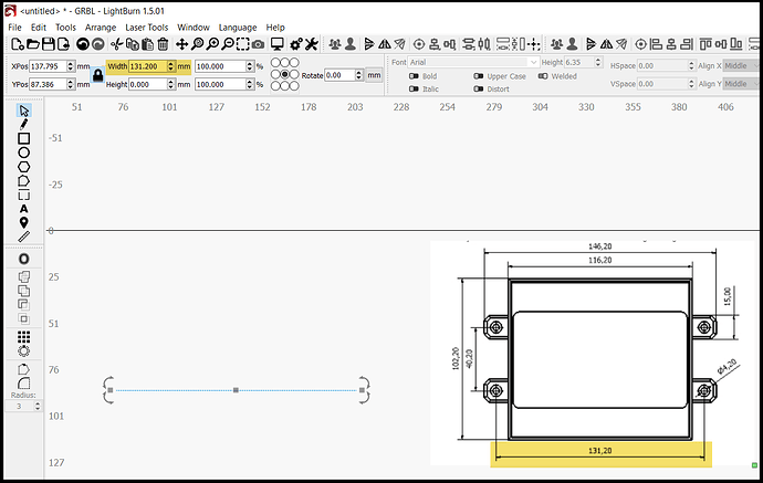
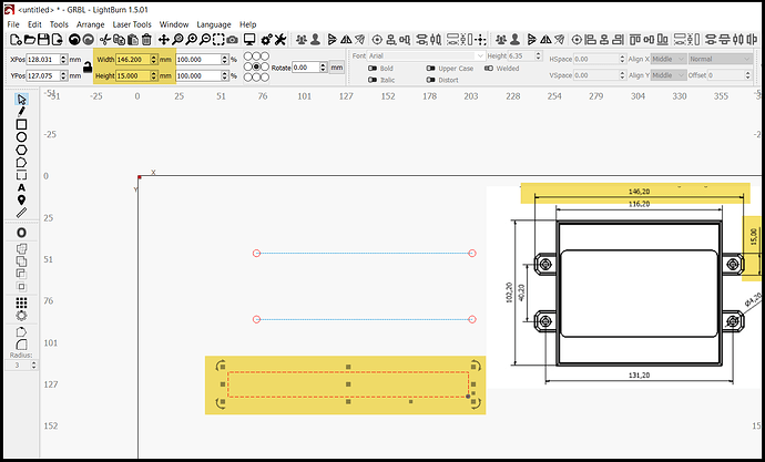
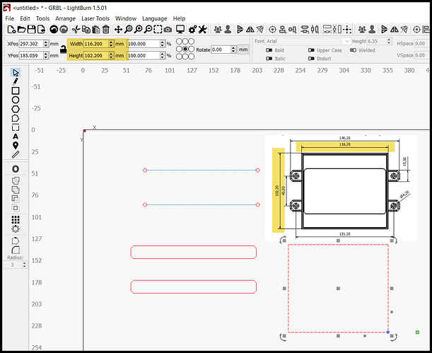
You have a blueprint of your design. The only dimension missing is the chamfer size, and I scaled it off of your drawing at 3mm.
It’s fairly easy to draw your image in Lightburn.
-
Draw 131.2mm line
-
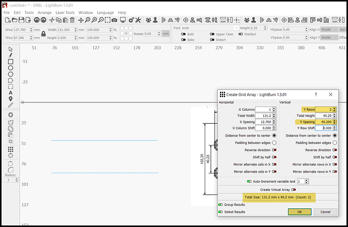
Array the line by 40.2mm on Y
-
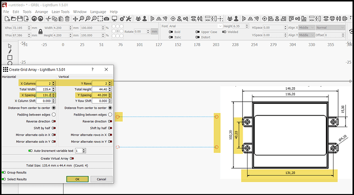
Draw 4.2mm diameter and place center on left point of bottom line
-
Array the circle 2 in X and 2 in Y by 131.2mm X and 40.2mm Y
-
Group the 4 circles and 2 lines
-
Draw a 146.2mm x 15mm rectangle
-
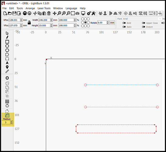
Put a 3mm rad in each corner
-
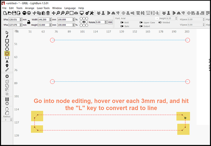
Enter node editing, and change each rad to a straight line
-
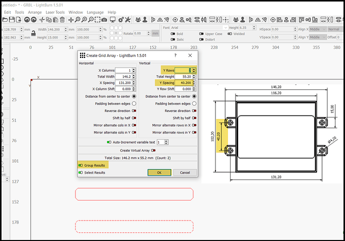
Array the rectangle by 40.2mm in Y and group results
-
Draw a 116.2mm x 102.2mm rect
-
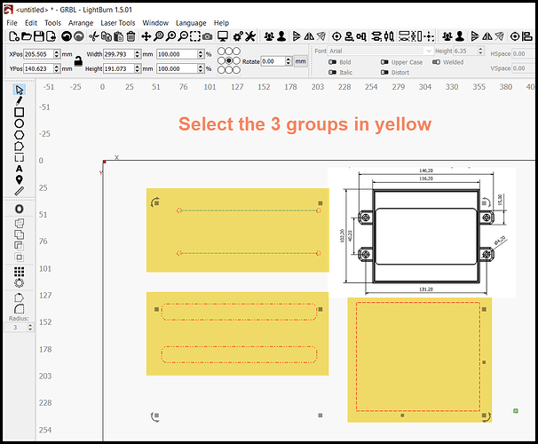
Select the 3 groups
-
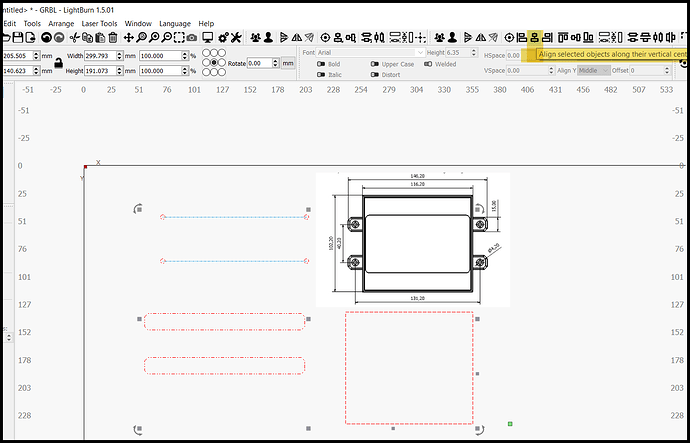
Align vertical
-
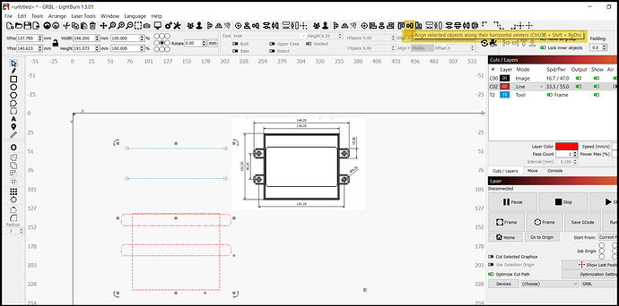
Align horizontal
-
Select the rectangles and boolean weld.
Thank you Very much, This is amazing and easy to follow
Nicely done @RalphU. ![]()
A good explanation and use of array.
This topic was automatically closed 30 days after the last reply. New replies are no longer allowed.
