hi im trying to swap a TL403CB to Ruida RDC 6442s-b ec i see similar instructions but not that exactly. Anyone know 1 can it be done, 2 what are the risks, and 3 if it can be done does anyone have a diagram for the swap already.
Before you swap it out, attempt to read out the internal settings, such as step length. You will need to set them in the Ruida once you replace it.
Most of these are relatively simple.
I don’t know what you want exactly…
Here’s a generic Ruida manual, maybe that will help.
Here’s the Topwisdom TL-403 manual.
If not, can you be more specific?

Help with a diagram to swap so I don’t do something stupid would be nice. I don’t want to blow out a part.
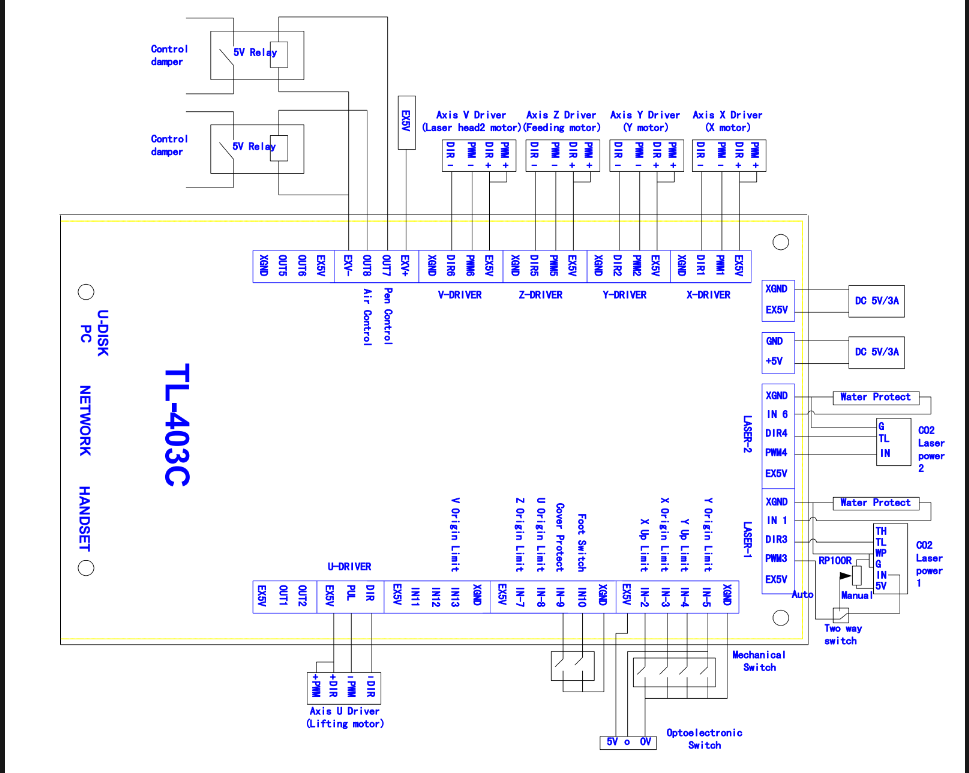
This is the TL-403.
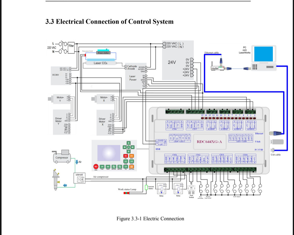
This is the Ruida.
I don’t know what they refer to as Y limit UP, unless they use these to detect an out of bounds with these switches.
The Ruida only needs to home with a pair of switches. For out of bounds, you need 4 more switches for a total of 6.
What part do you need clarified?
Thank you. That is very helpful. I think at this point I just wanna make sure that because the language isn’t identical between them, maybe you could give me a conversion guide on the names I think between those two I should have enough.
I look at these now and then, don’t know them and have no way to measure what I see if I don’t have one.
There are some slight differences, such as X origin limit would likely be the home switch input, on a Ruida it’s X-. All minus inputs on the ruida for switches are normally a - sign. The + sign is used for limit switches. It takes 6 switches for this to work on a Ruida, so you normally don’t see them.
On the Ruida you want the coolant flow sensor to connect to the Ruida, not the lps. The difference is that when the Ruida senses the fault, it halts everything, so you can continue with it when you fix the fault. If it’s wired to the laser, it doesn’t know and the head will continue movement without the ability to cause it to lase.
The basic interface to the stepper motors look standard. They wire Direction to Enable, I don’t think mine do that, but I’ll have to look, they might have a jumper there rather than running a separate wire.
The controller on a Ruida, determines what the motor takes, I guess in Chinglish it could be taken as a pwm signal. I think it’s steps, meaning PWM on the stepper motor output.
Ensure you get all the data you can off the original controller.
Did this help or ensure you’re more confused than ever?