I create a simple shape and assign it to the tool paths (T1 or T2). I was under the impression this shape (or any other) would be traced once the command was invoked. However, all I get is “You have no layers in your project set to output” ?
Seems odd as “Frame” looks to be the primary function of a Tool Path?
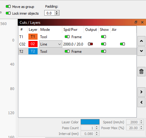
Tool Layers are used for creating non-output shapes in your designs . These layers have no cut parameters and will never be output to the laser. For example you could use them for: Indicating pre-determined material size and position on your machine. And since you have the 02 Line layer set to “No Output” it will also not frame
Did you notice there is no Output switch for T1 or T2? T stands for TOOL. You use tools, not output them.
The Frame is there so you can trace the borders of your material, if you set the box or circle/oval to that size, to ensure you are centered over the material.
I use the T1/T2 layers to help keep my designs within the borders of the material under the laser. Handy tool.
Yes, Mike & Loren. Thats exactly what I want to do. Create a shape,assign it to a tool path, and use it to trace on the material to be cut or etched so I know my design will fit in a certain area. Before this, I have been assigning a shape to any other layer, setting the output (line), then tracing…I have my settings to “turn on laser when tracing” with very low power of course. Been doing it this way for a few years. Then I started to try and use the tool path to do the same thing. I realize there is no output option-because its supposed to be a tool path, obviously. Thats why I want to get into the habit of using the tool path…but like I said, the laser doesnt want to trace…with just the tool path turned “on”.
Tracing only works on images (jpeg, bmp, etc). It does exactly what it sounds like. It overlays (like a sheet of tracing paper) the image and draws vector lines (paths) around areas of predetermined contrast difference. Once the trace is complete, you can separate the two, or delete the image. Or modify the traced lines and mask the image. Etc. Since its only purpose is to create a path from raster data, there is no reason to use it on an existing vector path.
Sounds like your overthinking this. Any line or shape you create on a “line” layer that’s set to output will burn that line/shape onto your material. Just the thin line. Like a pencil stroke.
Any closed shape (a square, for example) on a “fill” layer set to output will fill that closed shape with countless thin lines so that it looks like a solid color.
The “tool” layers are layout aids like guide lines that you don’t want to actually burn but help you place your workpiece on the bed or place your design within a prefab workpiece (like a coaster or dog tag or metal business card.). Use the tool layer to create a business card sized rectangle, place your design inside that rectangle, then use the same rectangle to frame and place the physical card on your bed. If you actually WANTED to burn a perimeter on the card, that could also serve the same purpose.
Further, any layer set to NOT output is essentially a tool layer until you set the output to ON.
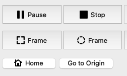
In case this is all misunderstood and you simply don’t understand the error, try doing the same thing but use the frame button instead of the start button. It will then frame just the tool layer even if there is no layer set to output. Although, I’m not sure of the purpose of such an exercise except maybe a mechanical alignment like squaring your cutting bed to your machine.
I just tested this on my machine. If you don’t have any cut layers set to output and click the regular frame button (the square one) it reports the error you have. If you activate your circle layer and use that frame button it will frame the bounds of your circle.
If you select the “rubber band” frame button (the round one) with your cut layer on it will frame the entirety of your workspace, cutting corners as necessary. If you turn off your cut layer it will output the position of your tool layer frame(s). In the case of your file shown above it would follow the extents of both of your tool layers since both frame switches are on.
If I simply hit the “Frame” button (bottom left in your picture) WITHOUT having the output turned on for the red “cut” circle, then I get the “no output” error. even thought the “Frame” for both tool paths are turned on.