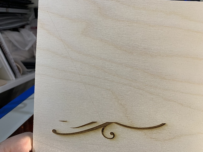
Traversal Burns have STARTED to occur

So I have had Lightburn installed for a while, along with my Awesome.tech MiniGRBL (1.1f), and everything WAS working ok.

Had a couple of issues with the machine recently, so installed a new tube, while doing so added water cooling, and stripped, cleaned and reassembled PSU.

I am now getting Traversal lines across some movements.

Firmware is 100% set to Laser Mode
I have previously set Max Spindle speed to 1818 (from 1000 which limited the 100% to around 16ma)

Although I changed this setting in the Machine Settings (GRBL), I had not changed it in the Device Settings (Lightburn) however it has not previously been an issue.

This evening as a test, I changed Device Settings Max Spindle to 1818 also, no change to results.

Concerned I may be looking at a failing Flyback Transformer, however thought I would ask on here in case there is something stupid I am missing.

Assuming that the Flyback was failing, I would have expected ALL traversal lines to burn? In addition, they are substantially fainter then the design burns (although I guess that could be a result of faster movements across white space maybe?)

Thank you

Console Dump below :slight_smile:

$0=10 $1=125 $2=0 $3=1 $4=0 $5=1 $6=0 $7=0 (ATC M6, pulse/ff) $8=100 (ATC Tool Td, milliseconds) $9=100 (ATC M6 Td, milliseconds) $10=1 $11=0.010 $12=0.002 $13=0 $19=0 (Softstart, milliseconds) $20=0 $21=0 $22=1 $23=3 $24=2000.000 $25=2000.000 $26=250 $27=4.000 $28=5 (Spindle freq. 0 to 15) $30=1818 $31=0 $32=1 $100=157.000 (x:stp/mm) $101=157.000 (y:stp/mm) $102=160.000 (z:stp/mm) $103=160.000 (a:stp/mm) $104=160.000 (b:stp/mm) $110=12000.000 (x:mm/min) $111=5000.000 (y:mm/min) $112=5000.000 (z:mm/min) $113=5000.000 (a:mm/min) $114=5000.000 (b:mm/min) $120=8000.000 (x:mm/s^2) $121=3000.000 (y:mm/s^2) $122=3000.000 (z:mm/s^2) $123=3000.000 (a:mm/s^2) $124=3000.000 (b:mm/s^2) $130=320.000 (x:mm max) $131=230.000 (y:mm max) $132=200.000 (z:mm max) $133=200.000 (a:mm max) $134=200.000 (b:mm max) ok! ![IMG_6298|666x500](upload://nrAEzhCV0CWaST9S3fiUoi4dTYm.jpeg)

Have you tried a pull-up or pull-down resistor?
This fixed the problem for me.

Absolutely no idea what that means :slight_smile:

Could you explain a little more, thank you

I will do my best but I am no electrical engineer and any messing around you do is at your own risk!


In my setup, yours may be different, the laser is turned on when the pin on my controller board is set to low, 0V. This pin is connected to the L terminal circled in red on the power supply as shown on the above picture. “Switch Laser Control: High Level(≥3V)- Laser Off; Low Level(≤0.3V)-Laser On.” If you take a resistor, I used a 4.7k ohm resistor, and connect it between L and 5V it will insure that when the controller board is set to high, L will read the full 5V and turn off the laser.

Thank you for providing the details you have, I spent most of the day reading up, and your solution reads similar to those I have seen others use.

Granted not necessarily with our setup, and your description certainly is clearer to read.

Can I ask, when did you have to implement this? Was it an immediate thing (the issue was always there) or did you have success for a while, and then the issue started to occur?

Thank you again

Pete

It was an intermittent thing for me. Sometimes the laser would cut traverse lines sometimes not. Sometimes the laser would turn on when I powered things up for no apparent reason. This was particularly scary! You said in your original post you have added water and cleaned the power supply. A little extra electrical noise here and there could affect a “floating pin” (not pulled-up or pulled-down). I would definitely start with a pull-up (active low to turn on laser) or a pull-down (active high to turn on laser) and see what happens.

Thank you,

You seem to know a little more about the Knowledge behind these.

I get the theory (but not the science) behind the resistor either removing any residual voltage, or stabilising it at a specific voltage.

But no idea of where to install or what resistance,

Obviously you have given the details of your Pull-Up ? (Guessing as stabilises the 5v)

Do you in know how it would work for a pull down?

Thank you again

Pete

Referring to the picture above again as a guide. If the power supply was active high then I would have put the resistor between the controller board pin and ground (G). That way the power supply terminal would be reliably sitting at 0V when the controller board pin was set to off.

So, no luck with the installation of resistor

Something I am confused by, if you look at the image below, you can see the initial traversal line from home, to the starting point of the design

However, they do not show up when burning the raster file, it seems quite capable of turning fully off and on for the bi-directional scans.

There are two things that might be at play here - There’s a “laser on” input (L) and a laser power input. When jogging, or traversing between cuts, the software uses G0 moves, which are supposed to disable the laser output. When engraving, the software outputs all G1 moves, and just varies the power between 0 and not-zero.

If the power supply fails, the on/off part usually goes before the power adjust part, so it’s not uncommon to see travel lines between cuts, but not within them.

So just to update

This evening installed original M2 board and Whisperer

No traversal lines occurring.

Tomorrow I will pop mini gerbil back in, and see if it starts to occur again. Will also try and find some alternative softwares to test it with.

Hopefully will be able to identify the issue as being either a software setting that I am somehow missing (that has been correct previously), a fault with the mini gerbil, or a fault with the PSU.

Luckily the projects we have upcoming can be completed on the stock board (just not as efficiently software wise)

This topic was automatically closed 30 days after the last reply. New replies are no longer allowed.