Trouble closing lines

I’m trying to close all lines on an vector, I start with 67 and now I’m down 19. My end goal is to create an offset and change to fill so I can raster engrave instead of vector engrave, This should provide a better end result.Logo.lbrn (123.8 KB)

Any help would be appreciated.

That’s an interesting image/file. Your objective escapes me, however. If you want to create an offset around the entire object and use line for the inner portions, you have to break and connect those segments which represent the perimeter.

It’s not particularly difficult to establish a single path in order to have offset work as you describe, but can you indicate/provide which path(s)?

Consider to “bust 'em up” into segments and put each segment on a different layer, for easy reference to describe your objective.

There are a series of shapes that can’t be filled unless they are duplicated and share borders with other shapes.

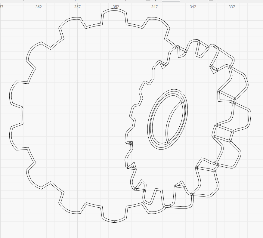
Just as an experiment, I brought your file up. I think it probably started life as a DXF file as there are so many inconsistencies consistent with that format. More than one or two duplicated/overlapped segments and a ton of non-connected segments that appear to be connected, but really are not.

I’m no whiz when it comes to this program, but I was able to make a properly joined/closed shape from the inner gear:

logo fixed sorta

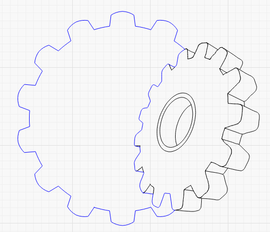
The blue section is now one continuous line, which may not be what you want, but it’s easier to identify this way.

I’ll attach this mod for your viewing pleasure.

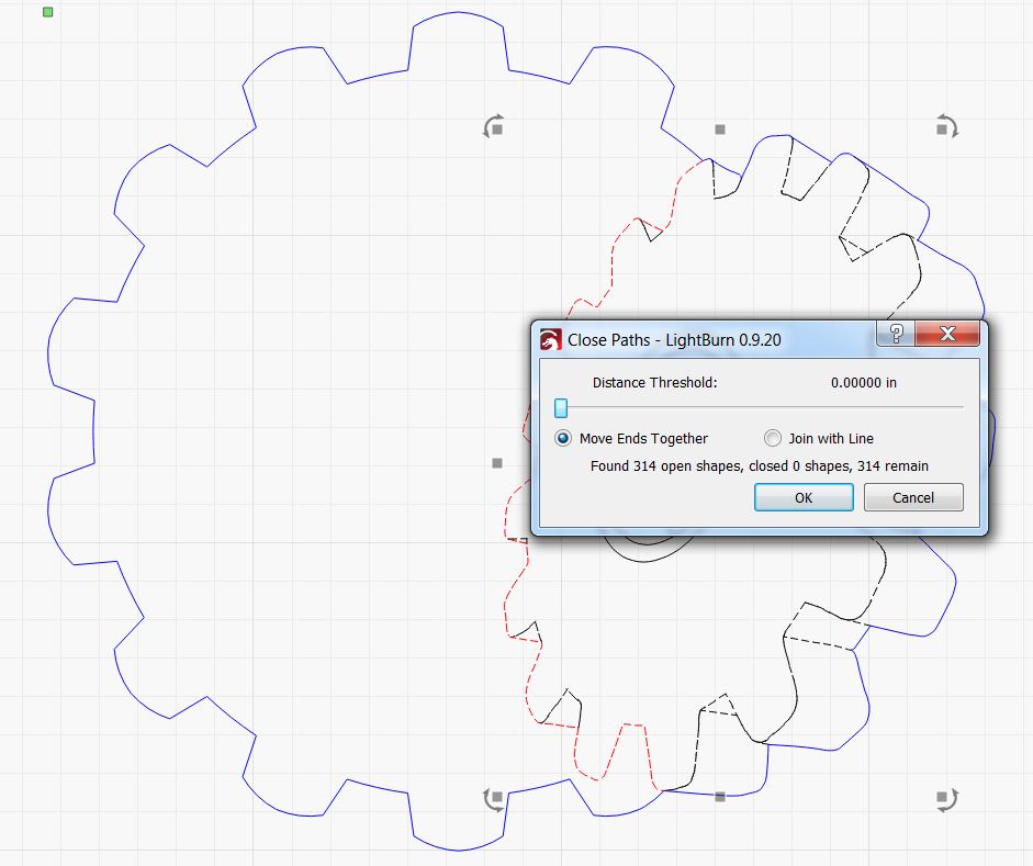
I learned a useful task this time around. The feature “close selected paths with tolerance” presents a dialog box suggesting to close with a line. You start with the “show me” button which selects those ornery segments, then use “close with tolerance” and close with a line. Use the slider to increase the tolerance until the line appears and the open shape count drops. It will then allow you to see exactly where the problem resides.

Oh, yeah, I had to use Arrange, Break Apart to get the DXF pieces to behave. That results in itty-bitty-tiny line segments that have to be “collected” and joined with Alt-J but it’s easier to keep track if you give them a temporary layer and turn off the layers you don’t need.

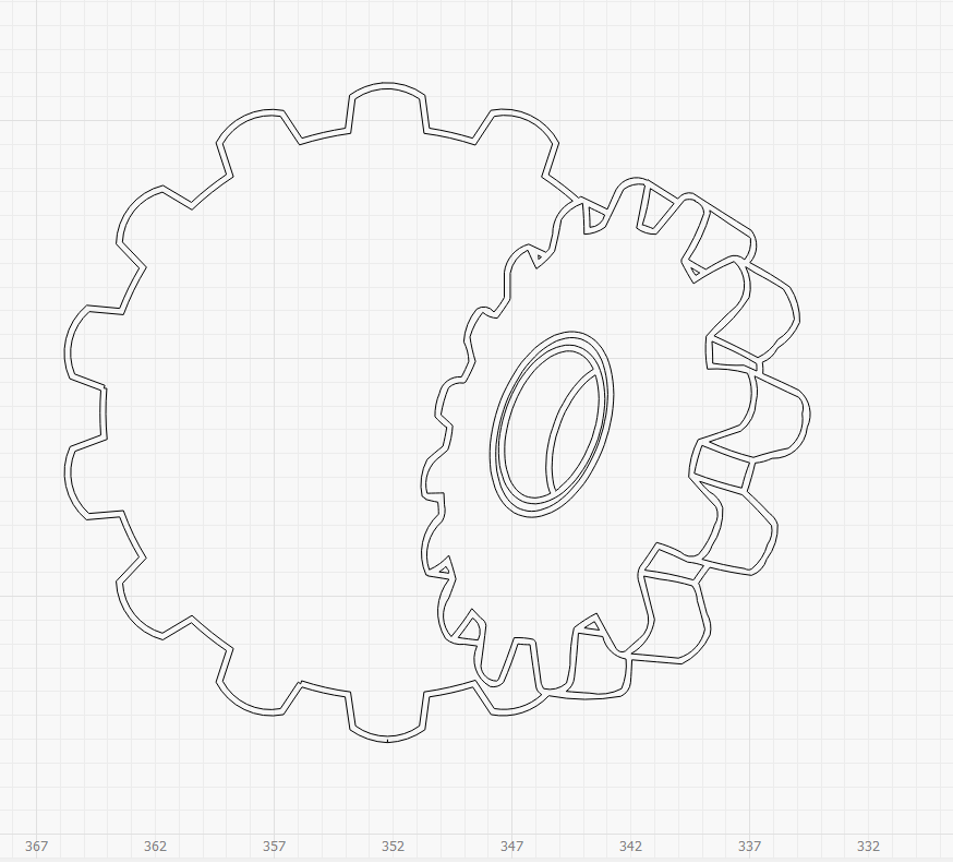
In case you wanted the outside of the entire logo to be closed, I’ve played around with that as well.

logo fixed sorta v2

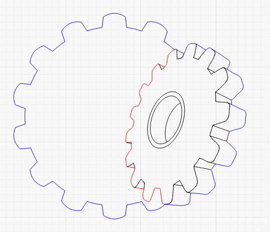
The previous collection of joined segments has been dumped on the red layer and the blue layer is once again a continuous/closed shape.

That file is also attached. Please note that my settings may not reflect yours and you should examine and adjust the power and speed as required, if any portion of these files work for you.

partly corrected Logo v2.lbrn (194.1 KB)

partly corrected Logo.lbrn (181.8 KB)

Thank you,

This is a company logo, we need to use it on lamacoids, vector engraving doesn’t produce as clean result as raster engraving on the plastic.
As it was, if I barely marked the surface with the thickness it was, this is why I wanted an offset and use fill.
You’re right it was a dxf to start. It had many unjoined nodes which I fixed. I noticed the segments that looked connected but no matter what I did I couldn’t get them to join.

I did that same thing you did to find the problem areas, but with my limited knowledge of the program I couldn’t get the problem areas to join up.

I’ll give it a shot and see how it goes, thanks for your help.

I just played with the files you attached, they show more open nodes now.

Were they all closed on your side?

This design cannot be closed without a bunch of work. There are places in this design that will require double or overlapping lines which can cancel out the fill. It can be done, but each shape must be distinct and closed for ‘Fill’ to work as you expect.

I have a different suggestion, have you tried to run this as ‘Line’, but have the beam slightly out of focus? This would give a thicker or wider cut line and also not burn as deep using the same power as defocused beam will deposit less energy and the point of impact with your material. I would suggest moving the focus away from the material vs into the material.

While that can be done, it is too much work as it would require more operations. All we want to do is change the text and burn. I have done the editing with overlapping lines, down to 2 open segments…

It’s not too much work for me, although it might not be too much work if you’ve managed to accomplish all but two thus far. If you care to attach the latest version, I’ll be happy to distort, disrupt and destroy the artwork. Oops.

I didn’t resolve all the shapes, as I had previously misunderstood your objective. I only corrected the innermost left side loop and then changed the attack vector (pun intended) to the outermost.

Knowing now your primary purpose, if it does not involve de-focusing the laser, a fabulously easy method to make a fill shape is to import to Inkscape, set the stroke to the desired thickness and then use Path, Stroke to path, which will generate an outline for every component.

Since I like to try new stuff, I did just that:

Here’s the before shot of the file after importing the inkscape work:

A ton of overlapping segments representing line segments expanded by Inkscape but originating in DXF, as expected.

I hit the overall shape in spurts with the weld feature, but some of the crossing parts vanished, so I did those one at a time. Some welded, some required boolean union, the one below the weld icon. Even that did not work for the back ring inside the small gear, which was probably an artifact from DXF/Inkscape combined. A bit of add-node, delete line segments, join, join, join (trim glitched on one end, but worked as advertised on the other) and this is the result, with a 0.25 mm stroke:


While attempting to create a preview, I discovered one obviously open shape, easily closed:

What kind of helper would I be if I didn’t attach the working file?

fully corrected logo.lbrn (126.7 KB)

Setting fill + line is left as an exercise to the reader, presuming the entire image is to become a stand-alone. Otherwise, my previous caution regarding checking speeds, power (and air) applies.

Oh, yeah, there’s a little spike artifact from the DXF at the bottom of the bottom gear. Maybe hit the node editor and cut it away, then rejoin the lines.

2 Likes

I understand, that is why I offered…

This topic was automatically closed 30 days after the last reply. New replies are no longer allowed.