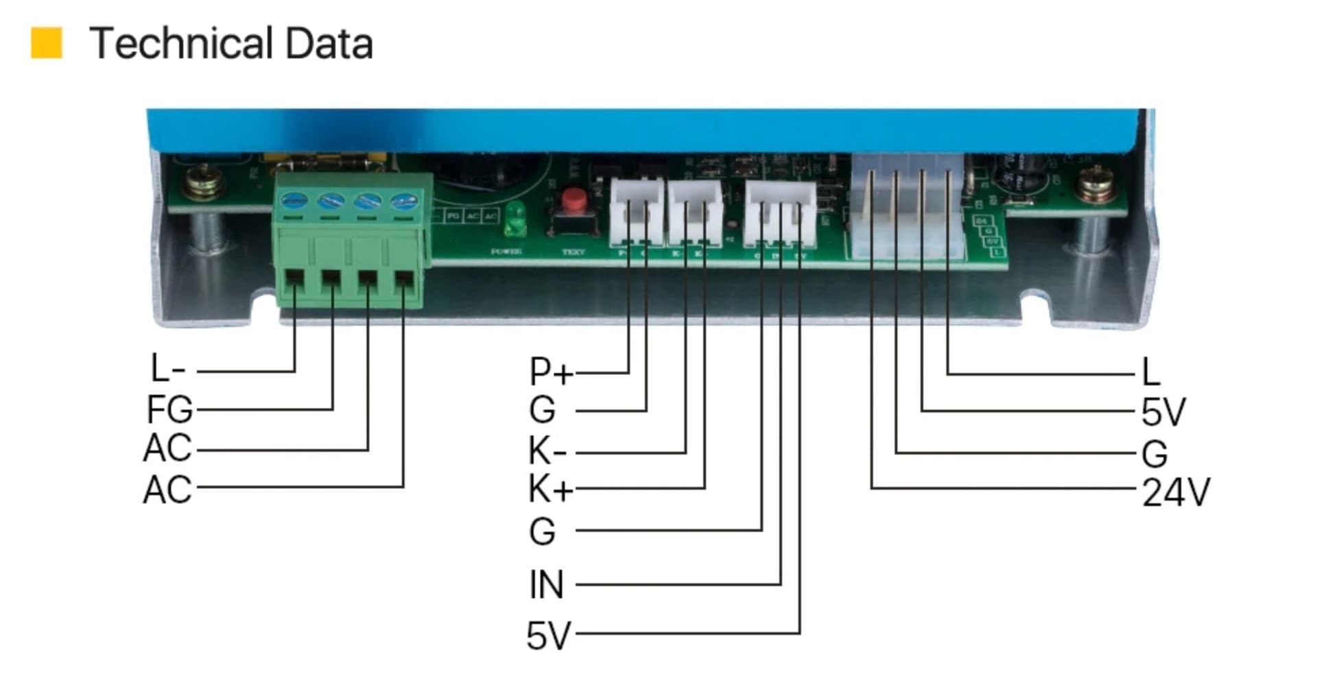
New custom build. Having issues connecting the Ruida 6445S to MYJG40 supply. The pinout on the power supply is a little different than what’s listed in the Ruida manual.
I currently have:
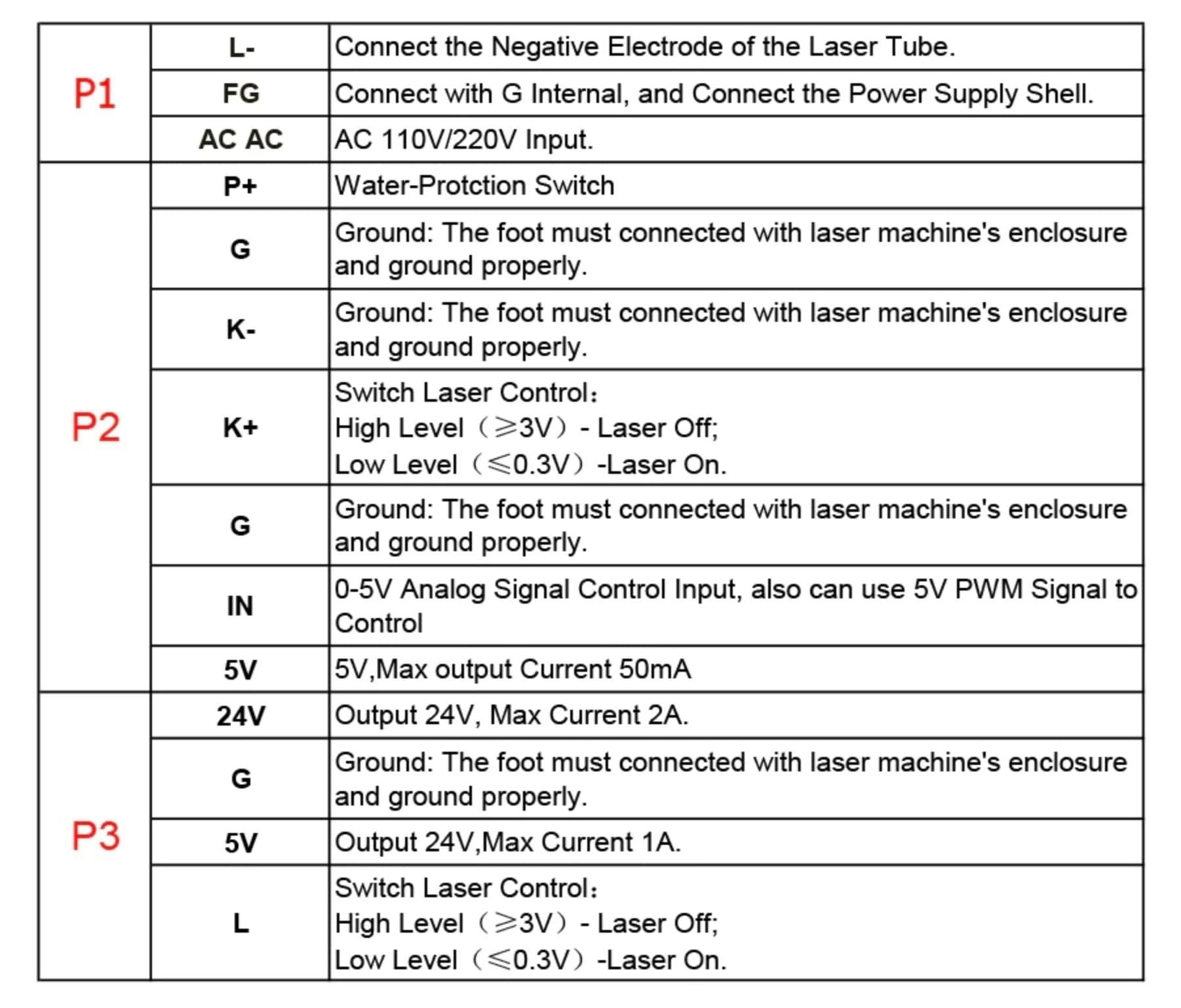
LPWM1 → ‘IN’
L-On1 → L (P3 on pinout sheet)
GND → G (P2 & P3)
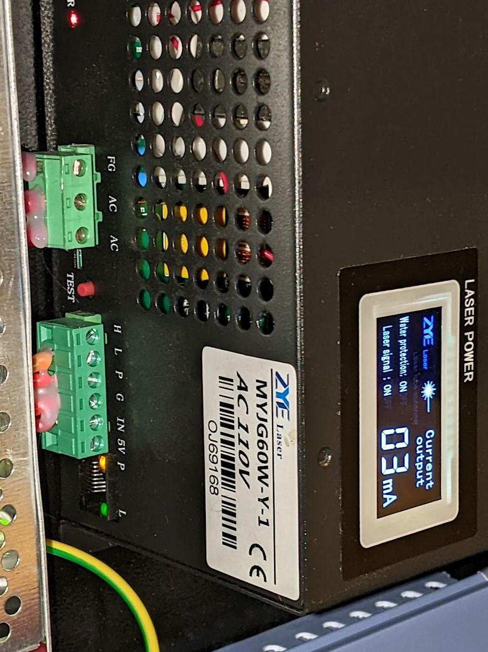
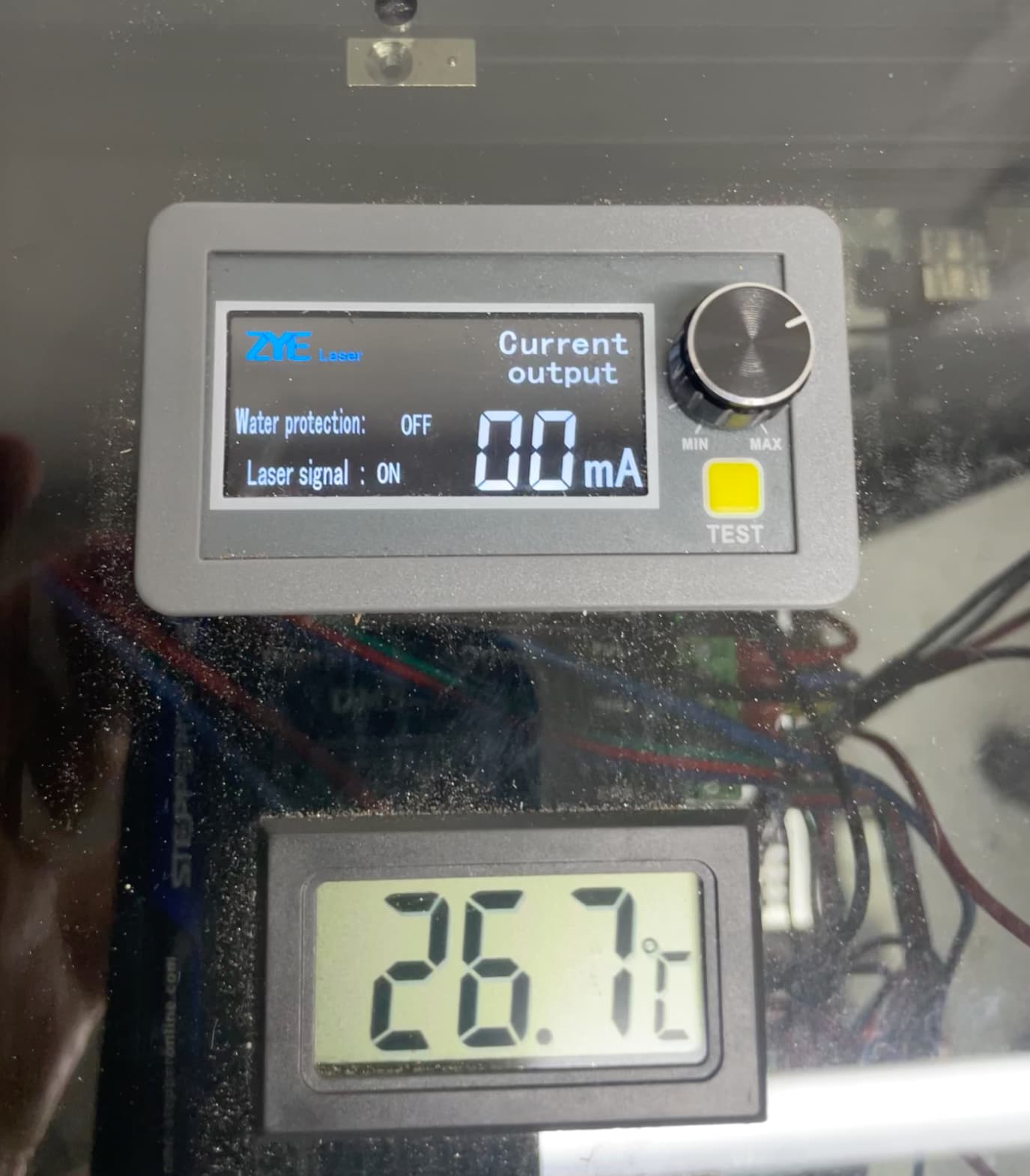
When I run a job the digital milliamp meter shows the laser signal but no change to the milliamps.
Pulse does not fire from the controller, but the laser does fire from the test button on the PS.
Any help would be much appreciated.
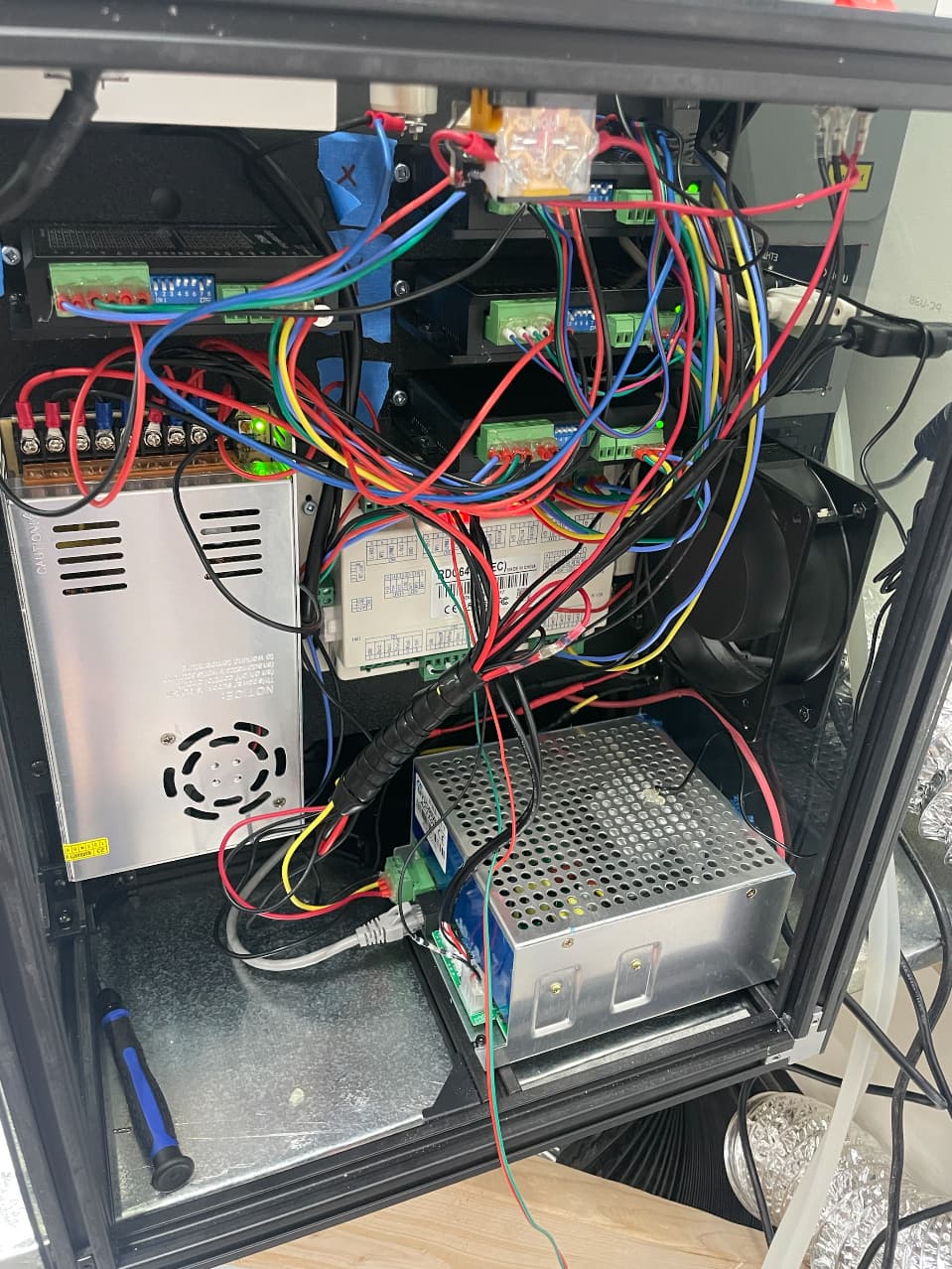
Ed, I really appreciate the help. Yeah, it’s the same digital milliamp meter only it’s connected to the supply via ethernet cable. I also have an analog inline meter tapped into the L- line. Here are a few photos of my setup. One of the photos shows the laser signal ON while pressing the pulse button (from the Ruida controller), but the laser doesn’t actually fire. It does fire from the test button on the digital mA meter.
I currently have the chiller water protect wired to the WP1 pin on the ruida board. Nothing into the P+/G or K+/K-. Perhaps that’s my issue?
Thanks Ed. For some reason, I don’t remember those being connected when I pulled it out of the K40, but I’m now looking at photos that do show a connection. Should I bypass it and have the Ruida handle the water protection or wire it straight to the supply? Possibly a way to wire both?
The flow sensor connects its two wires together when the water is flowing, so a wire from the sensor to both the supply’s P+ and the controller’s WP input will do that. The other flow sensor wire can go to a ground terminal on either device.
I did that for the lid sensor on my 60 W laser. Both the controller and the power supply will refuse to run when the lid is up:
If your laser still doesn’t fire, then you must also short the K+/K- terminals or wire them to the lid sensor or whatever.
I wired the chiller to both the power supply and the controller just as you said and everything is working beautifully! Time for the fine-tuning. Thanks so much for all of your help!