Trying to dial in DPI. but I feel these dots are hindering me

I’m trying to dial in my DPI for my Galvo. For some reason, I lay down the test gradient, and where I believe there should be a space (black anodized aluminum is the test piece) or just plain black, there seems to be a burst from the laser firing. I tried reversing the image to the negative, but that was not the problem. It also seems to do it between the spaces of fonts as well. I thought my speed might be too high, but it seems to get worse the slower I go. I’m down at 50mm/sec in this shot and it still does it.


I feel like this might be some kind of a lead in time thing, because of these odd markings on the text as well


Any thoughts? Anyone have this experience? Laser everything’s tutorial didn’t seem to mention this.

I see what you are talking about… I’ve never seen anything like this…

I’ve seen the blob at the start of the scan, but not during the run. Almost looks like the power has increased.

Maybe @JTR has some idea of what’s happening and what you can do about it.

:smile_cat:

1 Like

Also, looks like something similar here that might be related.


Is this on a CO2 Galvo? This might be related to FPK - First Pulse Killer. Galvo Settings - LightBurn Software Documentation

This won’t be the whole of the solution, but I would also enable the dot width adjustment and play with that setting a bit to get a gap between bursts: Tutorial: Perfect Image Engrave Settings - LightBurn Software Documentation

1 Like

No, this is from a Fiber Galvo

Switched from 110x110 lens to 210x210 lens, changes the dynamic but the burst is still there. Shows better here that it is on the start of the new line.

I work in MIG welding torch design, this seems reminiscent of the higher lead in amperage required to get the welding wire to turn molten. Almost like a lead in for each line ramping up at the start.

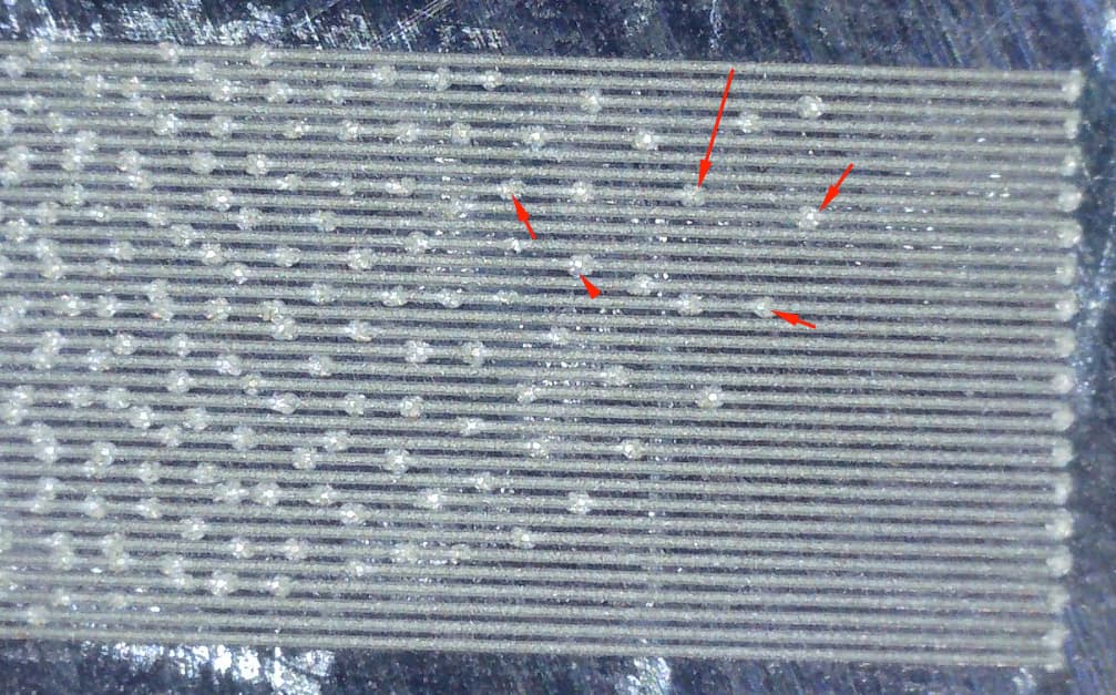
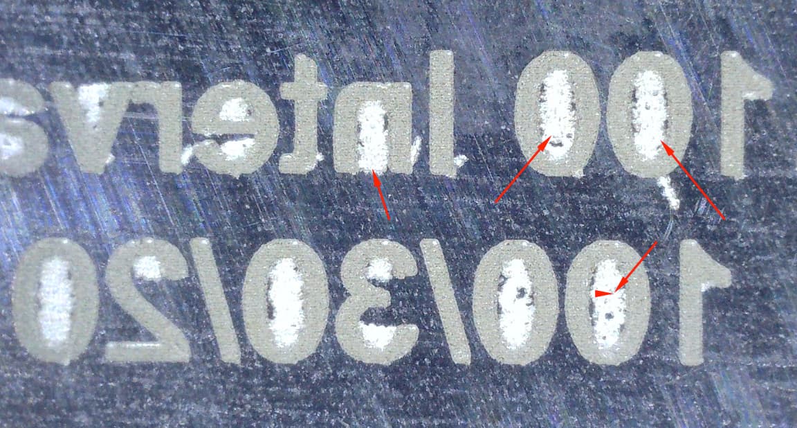
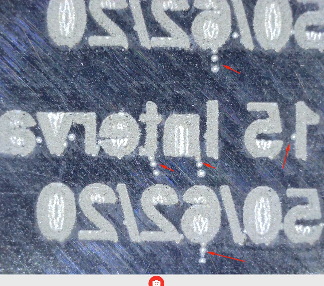
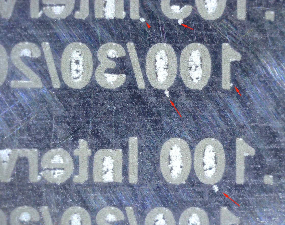
I’m seeing two distinct defects in the result you’re getting.

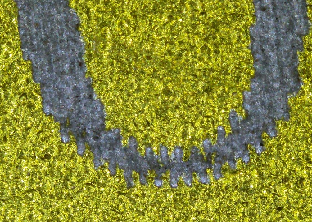
The trailing dots, marking between letters, and misaligned scan lines could be the result of poorly tuned Jump Settings.

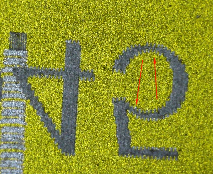
The dots you’re seeing in the middle and on the ends of scan lines could be caused by too short an On TC or too long an Off TC delay, or could be due to the relatively low frequency setting you’re using.

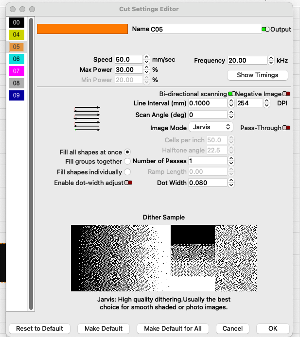
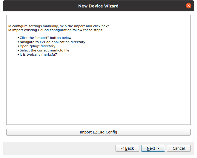
As a first check: if you did not import the markcfg7 file from your EZCad folder when you first set up your device profile in LightBurn, try doing so now. That file contains the timing settings EZCad uses, and they are usually adequate.

If you already did import that, and are seeing the defects anyway, try increasing the Min and Max Jump Delays in Edit → Device Settings. You may also want to try decreasing Jump Speed. The Jump Delays control how long the laser waits before firing after a Jump, which gives the galvos time to settle. If they don’t settle enough in time, you can get scattered marks like you’re seeing. Slowing the overall Jump speed can lead to less settling time being required.

For the dots in the middle and ends of the scan lines, try increasing frequency as a first step. With relatively low frequencies, each pulse of the laser has more power. That can sometimes lead to even more power at the starts of lines, and produce defects like you’re seeing. Those dots in the middle could be some other relatively powerful bursts, or they could be where lines are starting and ending in the middle of the image you’re testing with.

For Images, it can sometimes also help to override the default On or Off TC timings. If increasing frequency doesn’t help, try turning off Bi-directional Fill and identifying whether the dots are happening at the starts or ends of your lines. If its the start, override the On TC timing for your image layer to be longer. If its the end, override the Off TC timing to be shorter. You can override timings for a layer by clicking “Show Timings” in the Cut Settings Editor.

For a deeper dive into these settings, check out this video on the Laser Everything YouTube channel:

3 Likes

OK, first thank you for all of this. From what you describe here, I seem to remember thinking this was a requirement, but when it came time it worked without it. I thought LB wasn’t going to function without this, when it did I thought, OK, I guess they did some kind of improvement that makes it not required. Can you point me to what I need to do to load this? Or is this an executable file or the like? I’ll try this first then get back to you. As I said,thank you VERY much!

Click on device in the laser window. Select your device and click edit.

Click next, then you should have this screen…

This is where the markcfg7 file is imported.

You can then click through until the end. Only what you changed is modified.

Have fun

:smile_cat:

1 Like

Well, I guess I know why I didn’t think I had to install anything. Trying it out now after I restart.

image

Thanks, this is actually just text. If I am correct dot width correction is for images? Also, there is a broken link on that article you sent FYI.

Thank you, this rectified it. Had to do with the Jump Min Max

1 Like

This topic was automatically closed 30 days after the last reply. New replies are no longer allowed.