This has likely been asked plenty but i am struggling to find anything on my search. Hopefully a simple resolution, I am learning to engrave powder coated tumblers ( and I have an order coming up so need to fine tune now )
What i have is:
Creality Falcon A1 10W & Chuck Rotary System
Settings used ( after material tests )
7500 mm/m - 50% power - 0.08 interval
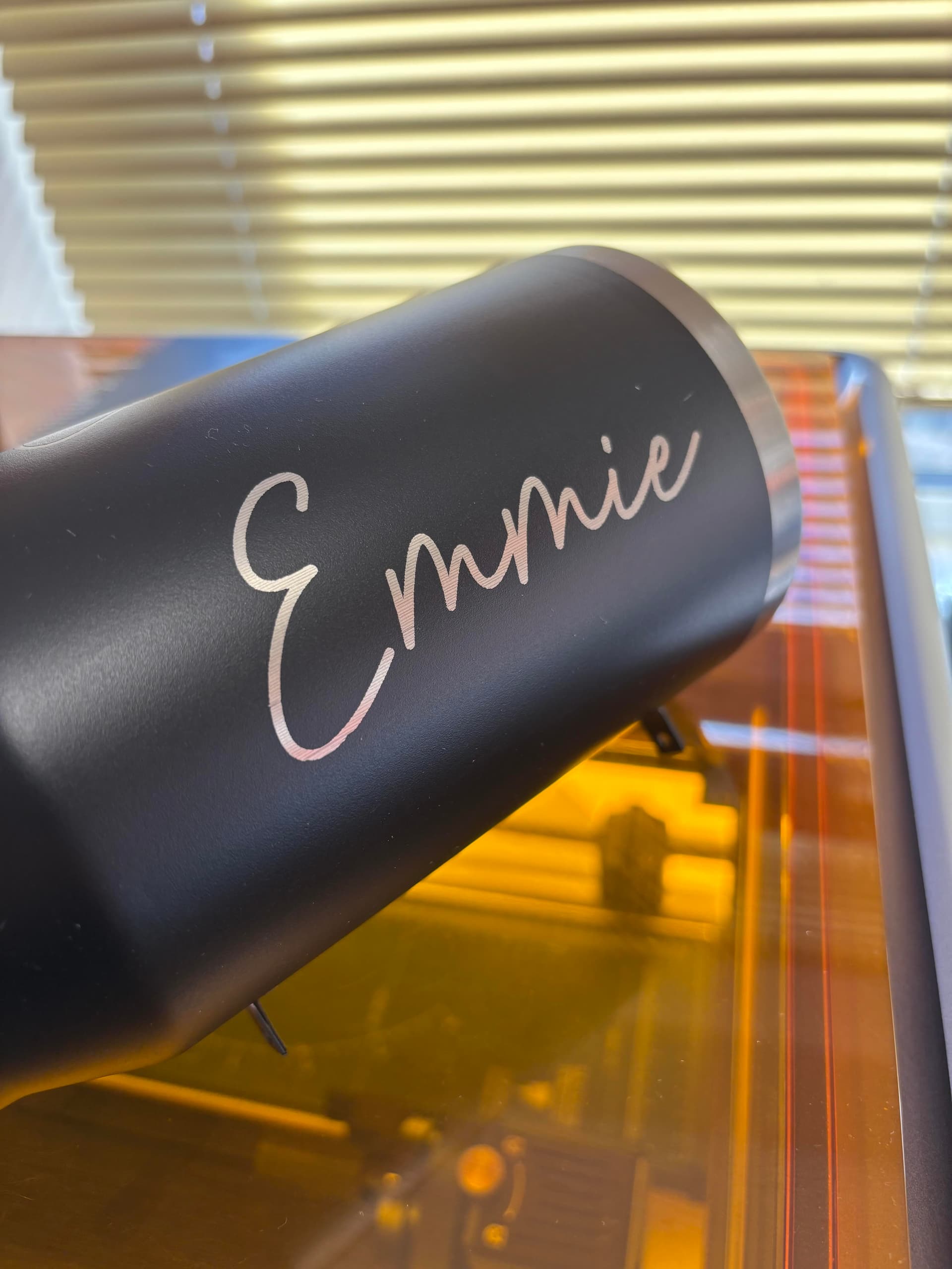
My issue being as you can see from the picture is the lines left behind after engraving and also what looks like part way down the design almost like the chuck has skipped ahead a slight bit. The chuck is tight as a tiger on the inside of the tumbler
Is there anything i can do to check or change to see if it makes an impact on quality - I have also given the engraving a wipe down with LA awesome and a microfibre cloth
So a few tweaks here and there this is where i am at
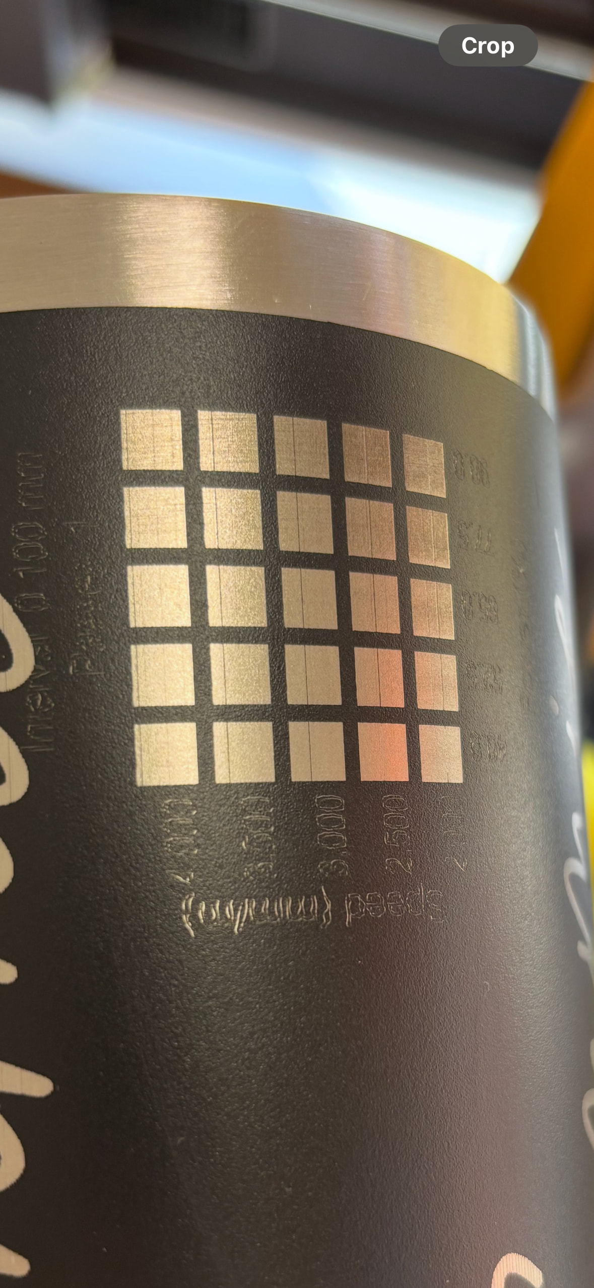
I have turned off bi directional fill and its yielding a much better result - however there is still this line that runs through the squares and its different positions on each square? The bottom right ive picked off with my thumbnail after washing with LA awesome and a scourer clean up but obviously i dont want to have to pick lines out of a tumbler
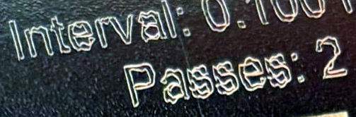
Then the second photo is honed in on the speed and power but i have gone for 2 passes to try and eliminate the line - would you say that the 3500 @ 50% would be a good finish?
I would make sure that you have set your diameter in the Rotary Setup window correctly - banding like you’ve shown is often caused by having a line or slice interval that is too small (along with a diameter setting that isn’t perfect).
Because the A1 is a CoreXY machine, belt tension is absolutely critical for proper operation: make sure they’re properly set up.
In addition, check everything mechanical in both motor drive trains to find & eliminate loose screws and sloppy assembly. The design of the A1 will make getting in there difficult, but it should work much better than it does.
Finding & fixing mechanical problems will be much easier without the rotary, using this test pattern:
Scale it uniformly to fill the platform and run it as fast as it will go in Line layer mode with Enable optimizations turned off and power set to mark a sheet of cardboard. Any differences from the design will be informative; a crisp photo will let us look over your shoulder.
So I have run the backlash file and image is attached. From this i am going to guess its more the rotary chuck that might be the issue instead but i am unsure how to check.
Also as there is a taper, i have tried using the taper tool but i am unsure as to whether i should be tapering just the artwork individually or the entire rectangular template?
The flat test is perfect, which rules out mechanical backlash in the XY machinery: good!
However, that means the chuck has backlash.
Assuming it’s that chuck rotary, I was unable to find the manual / doc for the thing. However, it looks like a direct-drive setup, with the motor shaft connected to the chuck and no intervening gears / belts / machinery.
If that’s the case, start by carefully examining the coupling between the motor shaft and the chuck, which may just be a hole in the chuck. There should be a setscrew locking the chuck to the shaft and, if that screw is loose, the chuck can wobble on the shaft. Search very carefully to find that screw and tighten it.
After that, the speed may simply be too high for the machinery to handle, leading to the chuck overshooting the desired position and wobbling back again. In the text layer for the Material Test:
Reduce the speed from whatever it is now (let us know!) to 1000 mm/min
Drop the power from 50% to about 10%
Run the tests again to see if the wobbling improves
That tells you it’s still turning too fast for the machinery to handle: the chuck + mug oscillates after large rotary motions. After eliminating mechanical backlash, the solution is to just turn slow enough to avoid wobbling.
Drop the rotary speed to 500 mm/min and the power to 10%, then to 250 mm/min and 5%. At some point the power will be so low as to not disturb the paint on the mug, but maybe you can find a sweet spot in there somewhere.
You can adjust the rotary speed with the GRBL Y axis maximum speed in $111. Save the current machine settings before you tinker, so you can get back to where you were before starting; saving separate Linear and Rotary settings will let you switch without forgetting anything.
Then run an Interval Test to find the proper interval for the focused spot size along the Y axis. Diode lasers (typically) have rectangular spots, so it’ll only be good in one direction, but that’s all you need here.
The results are headed in the right general direction …
So attached is the settings for the rotary speed etc - my set up rotates on the z axis but still its set at 10,000 do i still need to drop it as low as 500?
Also am i to assume that speed you put in the layers is nothing to do with this setting? Thats the laser speed?
Will do the scanning offset for now to check that too unless i was meant to do this first
All rotaries use the Y Axis driver, except those using the A Axis, U Axis, or Z Axis. Tweak whichever axis spins your mug.
The LightBurn speed sets the intended speed along whatever path the head is following.
The controller’s speed setting for each axis limits the maximum speed parallel to that axis. The laser head can travel faster than those limits when two axes are in motion: a diagonal motion (45°) will run √2 = 1.4 times faster than the X and Y axis limits.
If the LightBurn speed requires a higher speed along any axis than the controller’s maximum speed setting for that axis, then the controller reduces the speed of all axes to let the laser head follow the path at the highest allowed speed.
So the trick here is to find the maximum speed for the rotary axis that lets it spin without wobbling when it stops. You can also adjust (reduce) the Z Axis acceleration, but that’s in the nature of fine tuning.
Again: Save a backup of the settings so you can return to where you were before you started.
Thank you again this is all helping me understand better - however i have noticed something when getting my laser in position there is some jolting from the rotary chuck for no reason i cant upload a video but when im moving the laser via the lightburn terminal ( on the X and Y axis ) the chuck head moves slightly . . . im not even sure how i would diagnose this or even fix this.
The forum admins don’t allow videos, presumably because of the huge file size relative to text & pix, so you must put them on Youtube / Dropbox / whatever and give us the link.
AIUI LightBurn sends only XY coordinates in the jog commands.
I think the commands appear in the Console window, perhaps with Show All turned on. If any commands specify axes other than X and Y, that would be useful to know.
Edit: It might be the controller’s path planner plotting a move with all three axes and having the Z axis change from minus-itsy to plus-itsy in the process. No real motion other than a one-microstep twitch.
That looks like the Z axis is doing a one-step twitch.
However, seeing the chuck move with a fingertip explains why it wobbles in use: the stepper motor should immobilize a direct-drive chuck. Fix that and the wobbles will vanish.
The most obvious problem is an absurdly low motor current, but something else may be happening.
For starters:
How is the motor current set?
What is it set to?
As far as a GRBL controller is concerned, the Z axis is always enabled and participates in the path planning. Ruida controllers have internal logic for rotaries that plug into their Y axis (or whatever), but GRBL assumes you’ve set up all the axes appropriately.
LightBurn has some internal logic controlled by its Enable Rotary switch, but GRBL runs the axes no matter what.
I am baffled by the lack of doc on the A1, so I’m not much help. AFAICT they do not have downloadable manuals for their products, not that the usual manuals have much detail beyond setting it up.
Starting a conversation with Creality’s support apparat about why their rotary doesn’t (seem to) have much holding torque might be productive, if you keep asking about motor current and how to set it.
It’s possible the driver is defective, but insufficient current seems more likely.
Thank you so much for all your help, i did however have a little thought when setting up “another” test item.
On the creality they send you the legs in sections to elevate the housing so that you can fit the chuck underneath - i decided to use all of the parts and make it as tall as possible, in doing so i was only using one bolt on the laser to hold it in place.
I have since taken one section of the legs out and been able to use both bolts on the laser head to secure it in place and i have run a few wrap projects and other bits and have found no issue.
So this was completely my error here but wanted to ensure that i came back and provided an answer to this so it wasnt left unfinished on my part
Thank you so much again for your help, it has helped me understand the laser as a whole but also apologies for being a bit daft and not using common sense on this fact