I do a lot of 3D Printing ( SuperSlicer / PreForm ) and sone occasionally CNC Milling ( Universal G-Code Sender ) on mostly GRBL powered machines and am fairly confident in their operation.
I’ve now also acquired a G·Weike Cloud 50W CO² Laser with a Ruida Controller and am now learning to set it up for use with Lightburn where I’m having some difficulties understanding how some of the Z-Axis related functions are supposed to work.
Having already watched a bunch of YouTube Videos I’ve now come across this Omtech Polar Setup Video ( essentially identical to my G·Weike Cloud ) where for each Job they run in the Video they keep changing the Lasers Focus Lengthminus the Material Thickness using the Lightburn Machine Settings which quite frankly seems very wrong to me - Shouldn’t this be only set once with Material Thicknesses be addressed BY defining a Material Thickness?
So far, I haven’t really seen any Video discussing it, but will Lightburn adjust the Z-Height of the Toolhead when doing Multiple Passes through thick Material or is this happening only once at the beginning of a Job?
If it DOES - Is there a Setting ( other than Enable Z ) that needs to be addressed for this to work?
If it DOESN’T - Where is the Focus being prioritized? At the Top of the Material or at the Center?
While I’m already at it - During the Setup Process of the Machine I was offered the choice between either a USB-Packet or USB-Serial Connection of which I recall choosing the former - Any thoughts on that?
Looked like to me they weren’t using the concept of material thickness in Lightburn at all so were manually accounting for that. So the focal distance they were calculating was 17mm - material thickness. It’s possible you could leave 17mm as the focal distance and then just define material thicknesses for each material but I’m not familiar with that mode of operation.
It does. There is a Z step per pass in the Cut settings if you want to do this.
I haven’t seen much to recommend one vs the other on that. Serial I think is more “standard” or common. Not sure what would drive this decision one way or another. I’d actually suggest going to a network connection if you can if you have a reliable network. Oddly enough there are fewer things that tend to go wrong in that configuration.
Not from what I’ve seen. The camera looks to be a standard USB model. There are folks here that have come up with network solutions for USB cameras but it’s not a supported solution in LightBurn. You’d be off roading if you went that route.
I thought I come back reporting on some of my findings regarding the Z-Axis Control issue in case someone else may be of need…
Basically, the situation is as follows with how Lightburn and the Machine interact with each other:
Lightburn by default operates the Z-Axis inverted which I assume has its roots with the Machine’s referencing Z-Axis Homing Switch being situated at the TOP of the Rail the Tool Head rides along - This defines the topmost position as Z=0 everything else is based on ( Z=25 being the Tool Head scraping along the Honeycomb Bed )
Because of this Operations with Consecutive Passes enabled and a POSITIVE defined Z Step per Cut (mm) value would start the first Cut at the Bottom the Material Thickness with the Tool Head then getting RAISED for each consecutive Pass - This is obviously not how this kind of operation should work.
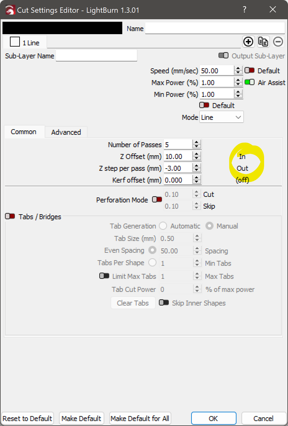
As far as I can tell - The Immediate Solution is - unfortunately - a PER Material Profile based one where we define a NEGATIVEZ Step per Pass (mm) value - Resulting in the Tool Head now getting LOWERED for each consecutive Cut:
Being able to set a NEGATIVE value for that setting has eluded me until I came across this Post which quite frankly I think should be replaced with an Invert Toggle Switch for awareness’s sake ( also In / Out should be renamed to Normal / Inverted )
I’d actually even go as far as to moving this Setting to the global Device Setting instead as I can hardly imagine someone making use of such feature only on a per Material Basis - Who the heck cuts most of their Materials Top to Bottom but some Bottom to Top!?
Besides the change to the Z Step per Pass (mm) we now also need to change the Z Offset (mm) as the Tool Head will otherwise still start the first Pass at the bottom of the Material Thickness instead of the top resulting in it crashing into the Material or Honeycomb Bed as it is now getting properly DROPPED with each consecutive pass ( instead of RAISED like before ).
IMHO, another Contender to either be entirely moved to the Device Setting or at least have it also available there to for the per Material Profile one to be ADDED to it.