I’m still in the very earliest stages of learning lasers and controlling properly with Lightburn. I haven’t explored much beyond basic function/control tests so far. I want to be able to control the machine predicably before I try to do any serious fine-tuning. I believe I have X/Y control pretty well managed now, so moving on to Z and Focus. This seems the most logical next place to go before attempting (if necessary) X/Y calibration. Need a nice burn to evaluate geometry…
Hardware & Environment
Ikier K1 Pro (22W). This machine has power Z with autofocus. Lightburn 1.4 on PC running Win10, connected via USB.
All three axes have mechanical limit switches (5 switches, 1 for Z, 2ea for X/Y). Home is bottom left for X/Y and full upward for Z. 410 x 750 x 40 travel limits (XYZ). Z has a second switch for focus, which can act as limit, but isn’t reliable since no contact lets negative motion continue until motor stall at mechanical limit.
Running in Absolute Coordinates. Relative Z. Optimize Z motion. (Questioning the Z settings…)
Machine Behavior (native/firmware)
Focus Macro runs head down to material. Contact trips a mechanical switch. Then the head moves up a fixed distance to produce approx 8mm between shroud and material. Get Position reports this as (Z)3.5, but I can jog down 7.4mm. The focus switch trips at 7.5 and errors out like a limit switch. I thought maybe the reported 3.5 was related to material thickness, but it’s not. Regardless of the material thickness, the auto focus position always reports at 3.5. This confuses me a bit. I could understand if it was ~7.5 (contact plus focal length) or a variable number based on absolute position. But, whatever. It’s consistent relative to surface, so I can work with it.
Focus Test
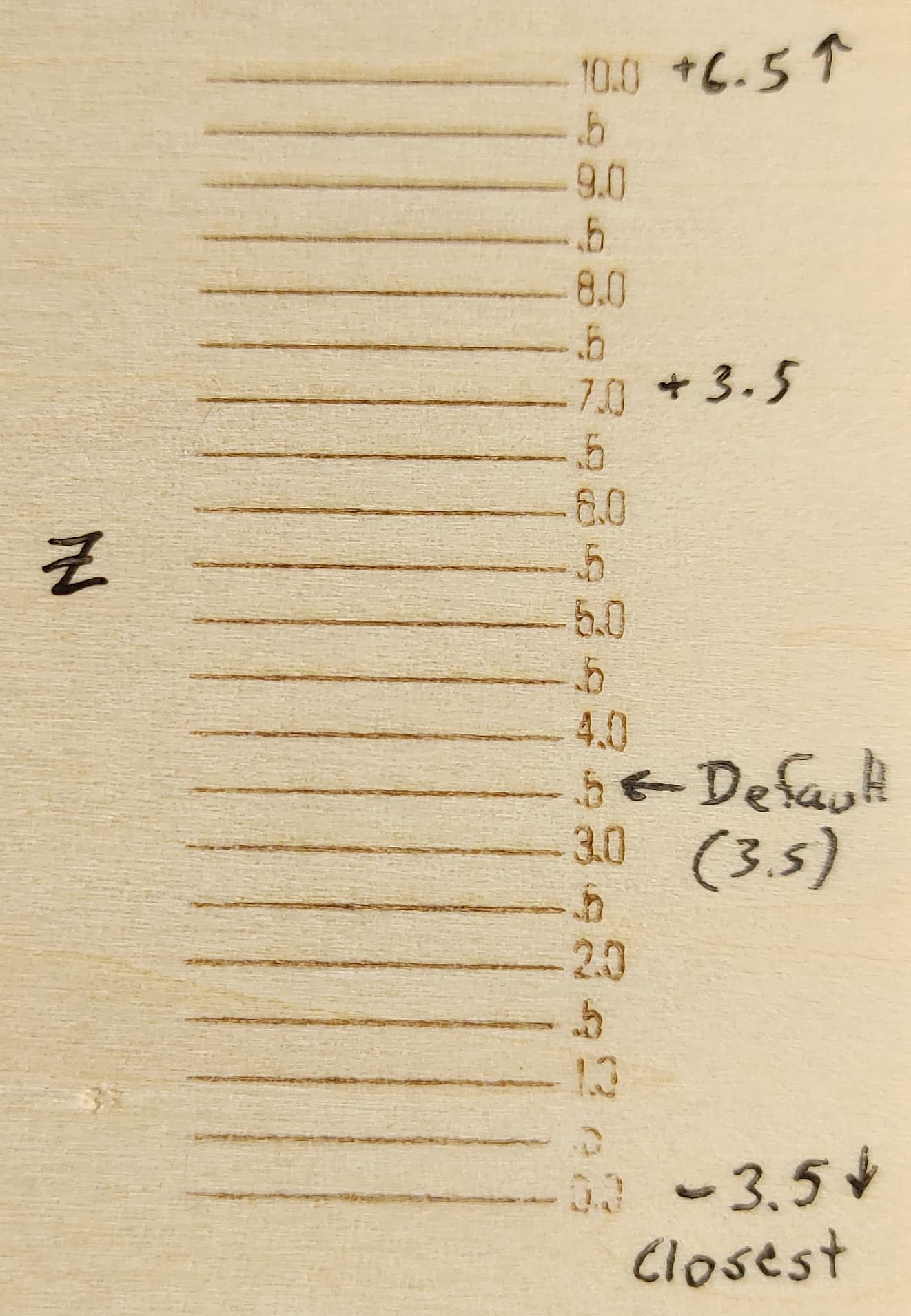
2mm basswood, 7000mm/min, 70% pwr.
It seems the test can’t do negative values and “0.0” is taken from current position at time of job start, so I jogged the head down 3.5mm from autofocus point (recall ‘focus’ is 3.5, so -3.5 jog reports as 0.0 in Get Position). This focus test was set for 20 steps from 0.0 to 10.0. This gets me an effective -3.5 to +6.5 from the pre-set focus. I just wagged those numbers, but they seem to produce visible change. I could probably stand to include another 5mm, but I really don’t think there’s valuable info there, except to explore useful limits…which is beyond the scope of this testing session.
I should receive my crack ruler tomorrow so I can objectively evaluate the test results but, to the naked eye, it appears I can stand to move my desired/ideal focus up by a couple millimeters. (See attached)
General Questions
- Does it sound like I’m understanding everything to this point?
- Is Relative Z and Optimize Z Moves the right way to set up this axis given my hardware and above noted reporting discontinuity?
- Can the X/Y location of the focus test be changed? It kept running near (but not exact?) center of bed. Not a big deal, but seemed odd given the ability to move the material test location.
- What’s the best way for me to set up a repeatable focus assuming I want autofocus (3.5) + (X)mm?
- How to best evaluate focus? I can’t really get a depth, so I’m limited to magnification, a crack ruler, and subjective edge quality (continuity, linearity, bleed/overburn, etc.).ie, what does “good” look like?
- Is there a separate cutting focus and engraving focus (ignoring z offset/sinking) I’ve been assuming a sharply cut shallow line also produces the best thru cut assuming Z is lowered as the cut deepens. Failing that, one usually lowers focus to near-half the material thickness to keep average intensity thru the cross section.
Tangential…- Can the Macro button(s) be moved? I would prefer to have my focus macro on the Move tab…
Thanks for making it this far! I do truly appreciate the wisdom of the elders here.
I WILL have more questions. Hopefully I will get to a point where I can give back something useful.