I’ve been able to narrow down a reproducible test case that demonstrates the unjoinable nodes issue. This is all done within LightBurn and doesn’t involve any imported vectors.
OS: Windows 11
Version: 1.2.01
Steps to reproduce. I’m working with origin set to front-left as that may determine orientation of objects created:
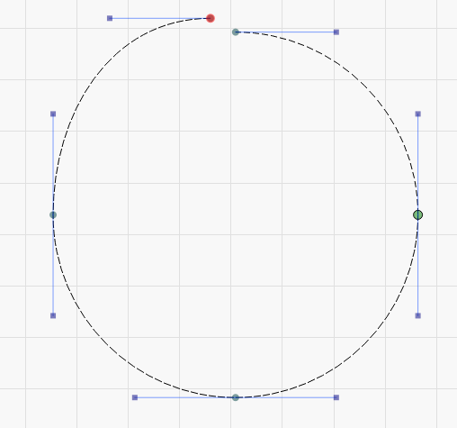
Create circle
Convert circle to path
Using Edit Nodes tool break the joint at the 12 o’clock position. This split joint will now not be able to be rejoined either by overlapping nodes or with close path. Breaking fully apart and then auto-joining will reform the path but the large start/end node will now be positioned in the 12 o’clock position, not the original 3 o’clock position.
This issue popping up has been a consistent sore spot but this has been the first time I’ve been able to come up with an easy setup to reproduce.
I hadn’t tried the insertion of a new node and removal of the end node trick as I’d be concerned with changes to the geometry. I usually get around this by breaking apart and then rejoining.
I tend to think this is going to be related to node topology but not certain.
Not able to reproduce your issue of not being able to rejoin.
However, with regards to the 12 vs 3 o’clock position as the starting point, a couple of processes to help address this are as follows:
Create a circle,
Convert to path
Break at the 12 o’clock position (path is deselected)
Select the top right quadrant of the path
Move the end node at the 12 away
Move it back (now reconnects and the Start point retains at the 3 o’clock)
My guess is the vector direction that the circle is created in, is in a counterclockwise direction. Therefore the starting point for the overall reconnected/rejoined path remains at the start of the portion of the vector you’re moving. Since you moved the top left quadrant, its starting point is just that, same as the point you’re moving.
I did the same thing of breaking the path at the other positions, 3, 6 & 9 and it became clear.
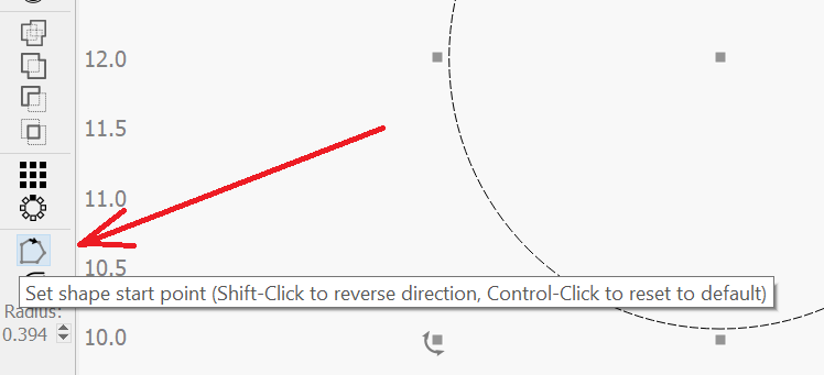
Now the second option may be simpler, just use the Set Starting Point button. Play around with it and watch the blue arrows around the circle change. Also, use the Preview button to validate where the cut/engrave begins.
What is the machine origin setup for your device? I suspect you’re not using front-left. If you’re front-right for your origin then the node at the 6 o’clock position is the one that will not be rejoinable.
I don’t think this has anything to do with vector direction as I can reproduce this in either direction.
I did set my origin to front left before testing to alleviate incongruencies is setup.
Small note of inconsequence really… I’ve worked as a software developer in my career and also performed “anti-testing” or “cross-testing” when validating end users reported issues. LOL.
You are correct on the default direction of clockwise. My bad.
Here’s something for you to test (and where I was lead astray).
Draw the circle
Convert to path
Break at the 12
Select the top right quad
Select the “Set shape start point” button, then
Select the 12, note the arrow direction
Select the 3 and note the arrow direction. Did the direction of the arrows change?
They do for me which is where I went awry on my conjecture that the default was Counterclockwise.
Also, I’ve discovered that holding the “Shift” and clicking the paths does not change the direction of the cut/engrave according to the arrows.
To make matters worse, if I continue to break the circle and attempt to show the direction of the paths, the arrows completely disappear and I can no longer see which direction the paths are taking unless I use the preview button.
Per your request, if I break at 6 then the path starts at 6, proceeds clockwise to 3, leaving the bottom right quad to itself. At the 6 (break point), I moved bottom left path away and successfully rejoined to the circle. I broke it again at the 6 and moved the bottom right path away and back and also rejoined successfully.
Thanks for confirming this. This is the same behavior I get.
How are you selecting just the top right quad? The entire broken circle is selected for me since it’s still a continuous although broken path.
Not sure what you mean by this. Do you mean to select the nodes located at the 12 o’clock position?
In fact, if I break any node other than the larger start/end node I do not get any arrow at all when using “Set shape start point”.
I think this is the same as what you describe here:
What is the location of the start/end node before you break any nodes? Is it at 9?
Clockwise or counter-clockwise? I’m confused by this.
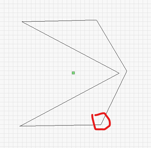
From what I can tell, this should be 100% reproducible anytime you break apart the node before the start/end node. More specifically, if you break the last node prior to the start/end node. This applies to any shape, not just circles.
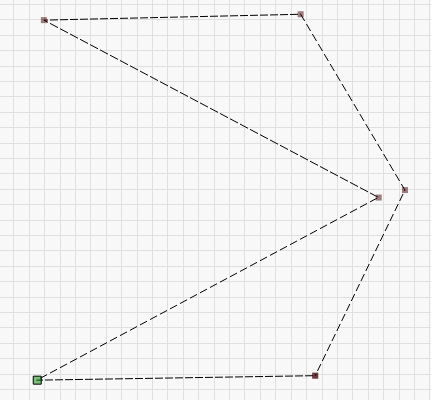
In this case, the problem is that the ‘drag-join’ code has issues when the nodes to be joined are “one behind” the beginning/end of the node list for the shape. In yours, the beginning / end nodes are the ones shown here in green:
This is a known issue and one we’re working towards fixing, but it’s not simple to do so unfortunately. I have it fixed and working with the other cases PY mentioned above, and will keep poking at it to see if I can figure out why this last one is being fussy.
I inserted a node on each line just a small distance away from the endpoints of each.
Then moved one of the endpoints out and back and the vertex joined.
Next I deleted the two newly inserted nodes and the shape retained its closed status.
At least it’s a workaround for those struggling until this is resolved.