Hey all, I recently got a rebranded Atomstack X7 Pro and I was a fairly disappointed when my engraving results turned out worse than my 5.5w unit. It seems like my 5.5w has a 0.08x laser spot, but the new M10 module is 0.15x0.15 and doesn’t seem to handle tiny details nearly as well at all. I’d like to keep the 10w laser as it has significantly better cutting speed and quality than the 5.5w, but I’d like a way to be able to swap the 5.5 laser for engraving work.
My 5.5w is a ‘Pergear L5 Pro’ (Not sure what this is a rebrand of) that uses a 3 pin cable. I’ve seen other posts where people want to upgrade their 5w unit and depending on the laser driver/power supply they need an adapter board- but from my limited understanding that’s just so the driver would have enough amps to not overwork itself and blow up. So I guess my question is: is there some kind of adapter cable or method I can use to swap these lasers out at will? I love the cutting ability of the 10w in comparison to the 5 but the amount of detail lost is pretty noticeable.
All advice, tips, or tricks seriously appreciated!
I can’t find any information on the M10 module but if it’s anything like the M50 then it likely only uses 3 pins of the 4 pin connector. In that case, assuming both the M10 and your 5.5W laser are both the same voltage laser then there’s nothing preventing you from just making an adapter from the 4-pin connector to 3-pin.
The wiring itself is dead simple: one wire each for Power, GND, and PWM/TTL.
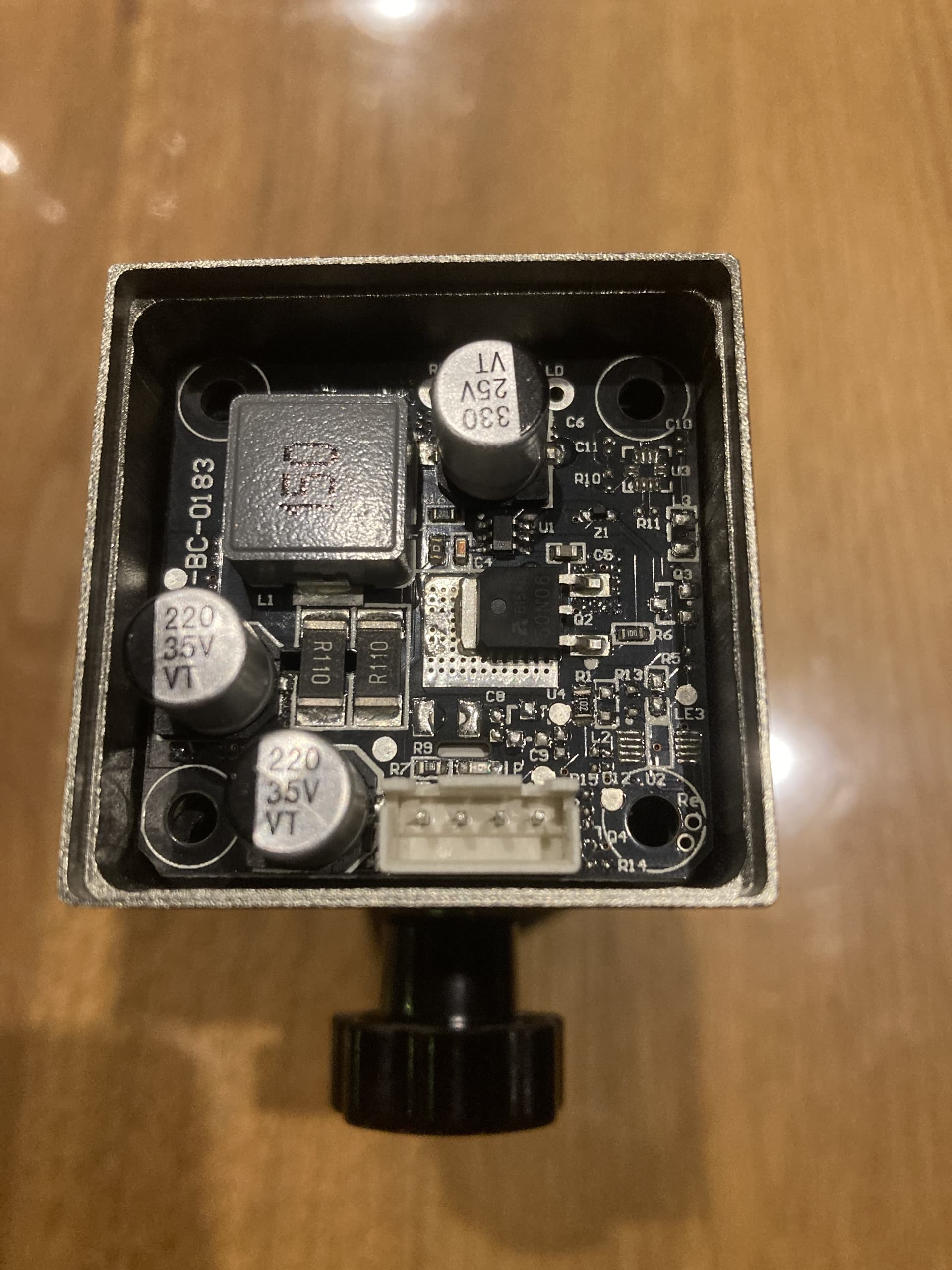
The L5 Pro actually uses an Atomstack branded M50 laser module so that’s definitely a good start. Looked at the 5.5w ‘L5 Pro’ and the M50 and they’re both 12v! So assuming I can make/buy an adapter then this should in theory work fine? Is there any way to tell which wire is which wire is which and does the connector type have a specific name? (That way I can buy a female 3-pin and a male 4-pin for the splice)
The easiest would be if there were markings on the board itself, either on the controller or the laser module then trace the lines. Otherwise you could just test the lines if you have a voltage meter. Power will be 12V, PWM will be between 0-5V depending on power level. GND is likely to be one of the center pins.
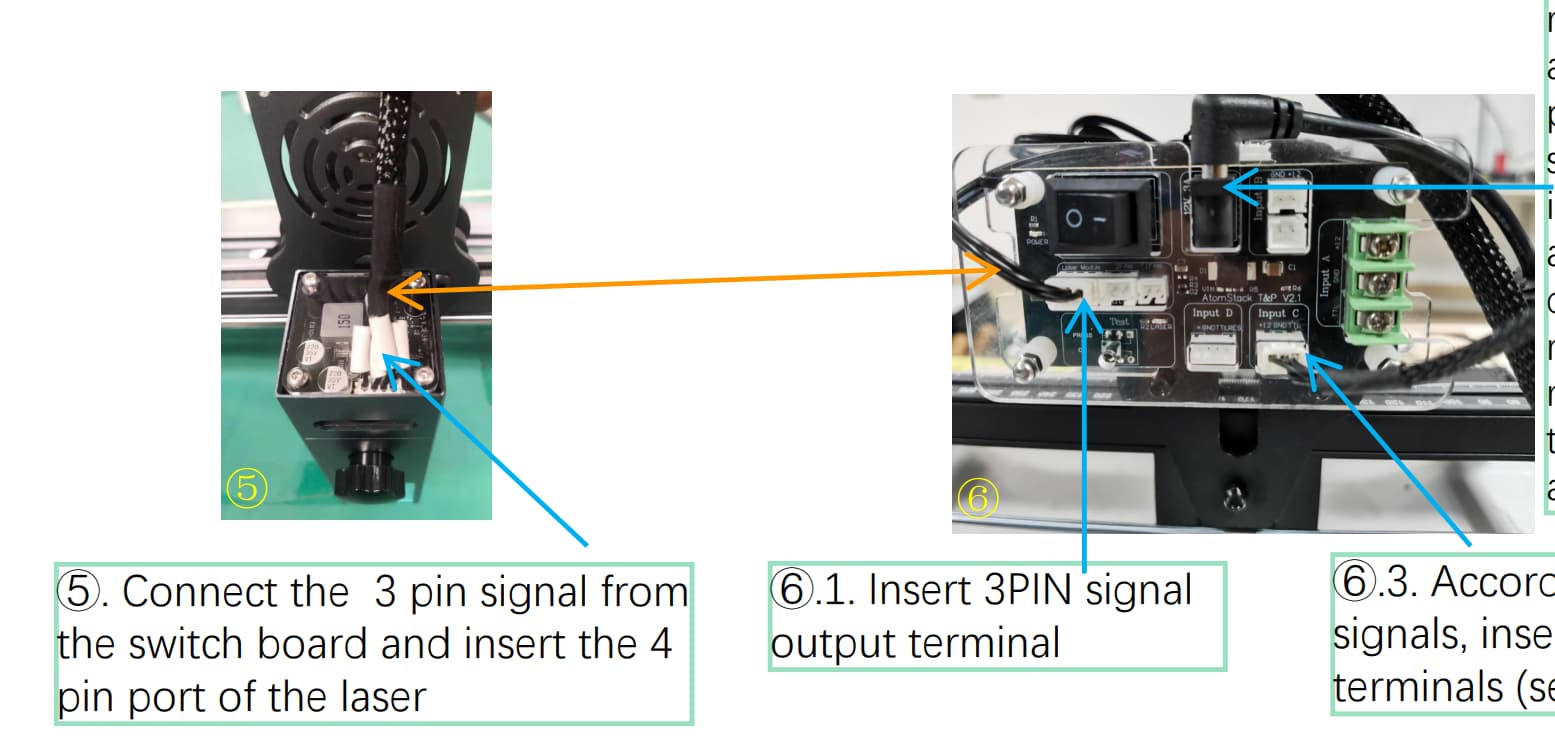
I’m looking at the M50 manual. They don’t use color coded wiring so makes it hard to see how they’re aligned but you can see how this works with the adapter board they include:
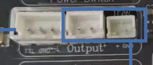
The connector on the adapter board is PWM/TTL, GND, Power with the keyed slots facing down.
Without having the connectors right in front of me I’d guess these were JST-PH… possibly JST-XH connectors. Measure the distance pin to pin on center. If it’s 2mm then it’s likely to be PH. If it’s 2.5mm it’s likely to be XH. Might actually be easier to measure across all 3 pins and average out so any error is less pronounced.
I think beginning from the left pin:
PIN1: 12V
PIN2: Ground
PIN3: TTL
PIN4: ?
Maybe it is a temprature signal.
Can anybody confirm the describtion of PIN1 to PIN3?
And what is PIN4?
Do you have the cable that came with it and the adapter board? If so, trace the wires from the module to the adapter board (which does have markings) to determine what the pins on the module are.
I have the same laser, on laser module on the other side of board it is written “RST” for the fourth pin.
Is that shortened for tipical RESET probabbly
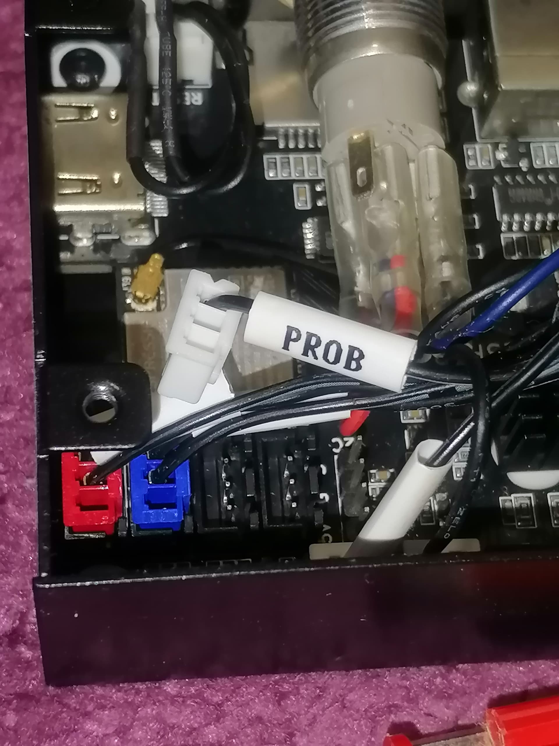
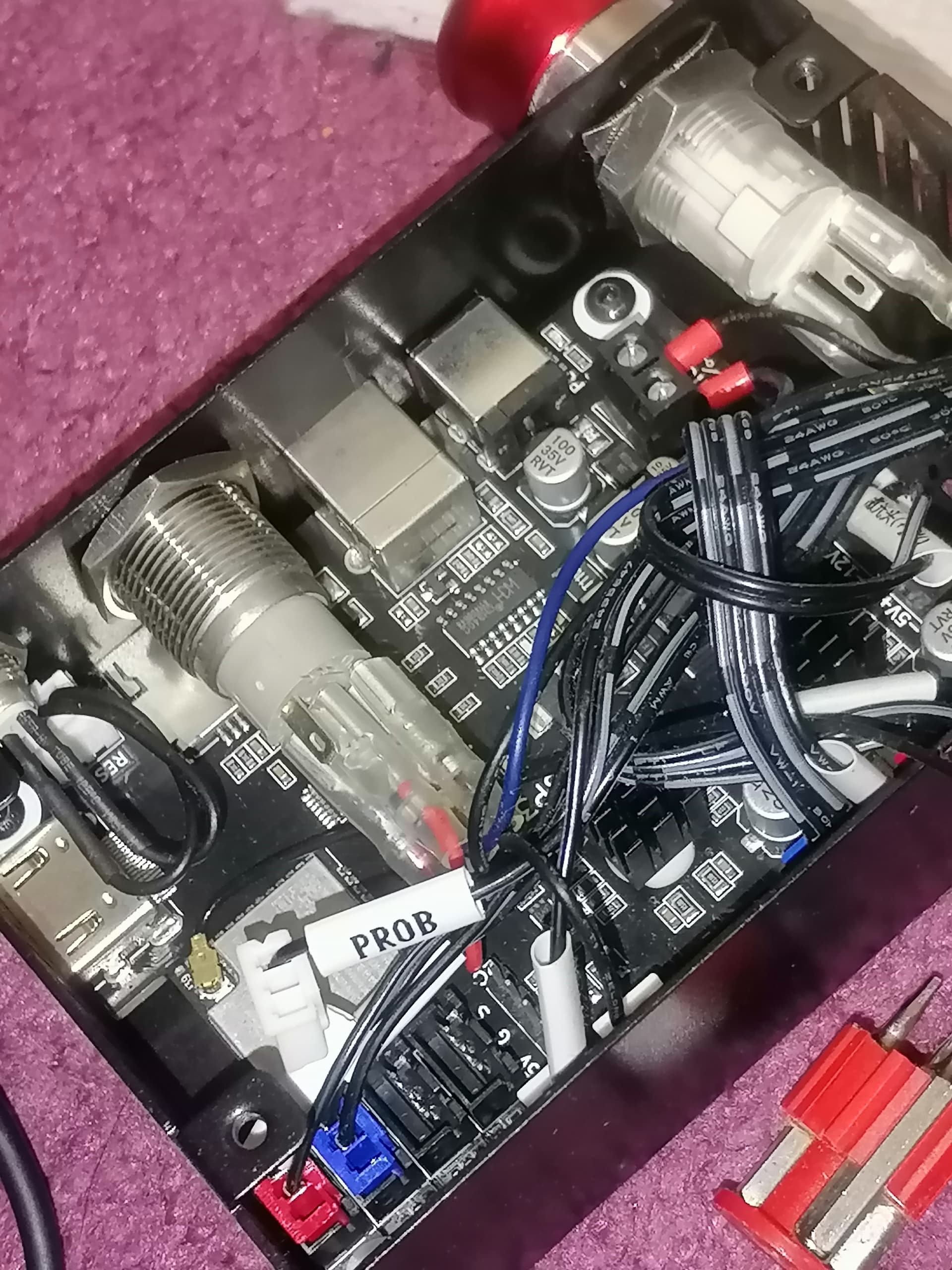
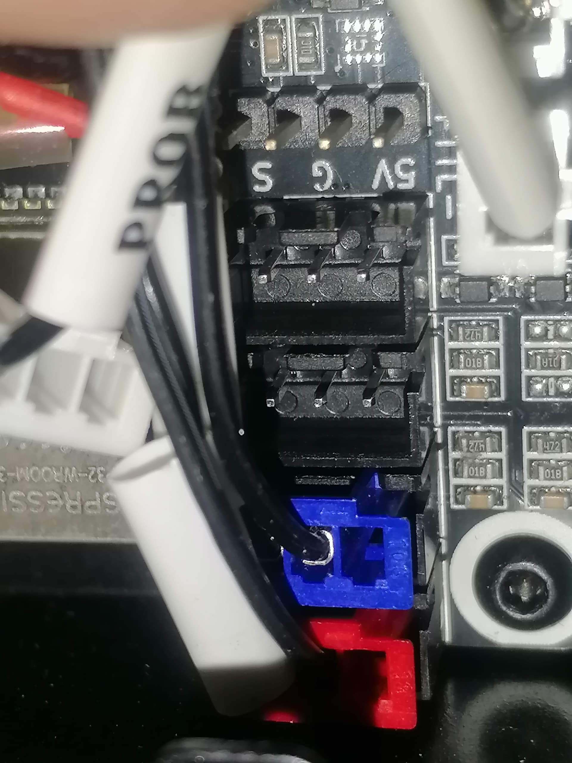
however, that same 4. wire “RST” is connected on main control board on signal pin “Z axis safety switch” (White connector PROB) : on picture you can see red and blue connectors for safety endpoint switches ( S , GND pin) while RST is probabbly programmed on ( S ) from Z-axis for reset…