Using lightburn as ersatz 2d cad progran

i am very happy with my first projects using this software for cutting small (and less small) parts to make functional small aeroplanes

so far i have not found any cad programs that offer functions that my very basic requirements need, affordable, and with a less steep learning curve

and thus, lightburn has stepped up quite nicely

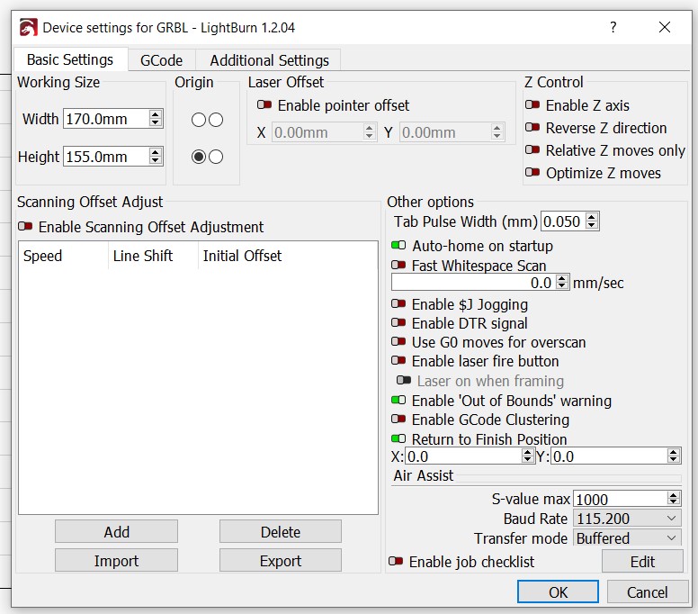
what i need to do though is redefine the work area to create rather simple plans for full working size of the models, and that would be great to do by opening into a newly defined work area

currently i’m using a neje master 2s, and with upgraded laser the available working area is a generous 170x155mm, perfectly big enough to do ribs in small batches

but for design, i reckon 1000x300mm would be the shiz, especially if the grid can be in 1mm increments with more defined lines at 10mm and maybe 50mm for ease of use

so, is there a way to define this design table, and if so, how do i access it without overwriting my current tiny but practical cutting table - they have 2 necessary but independent uses, and it would make my enjoyment of this program even greater

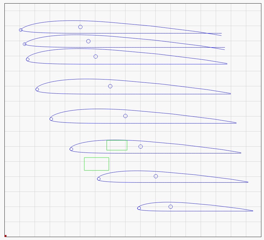
as a f’rinstance, here’s the ribs for a radio controlled discus launch glider (right size for burning)

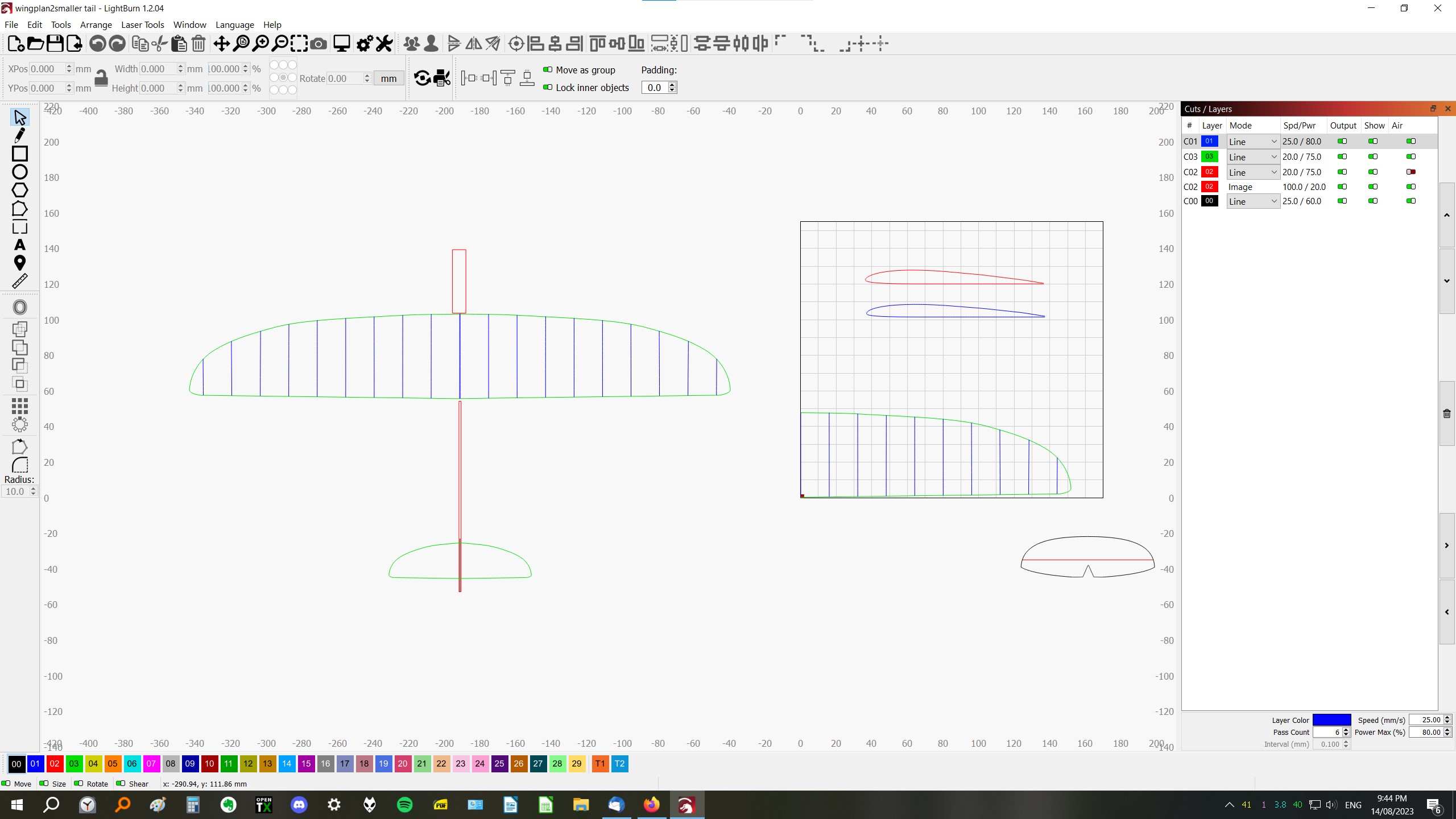
and here’s a wing plan

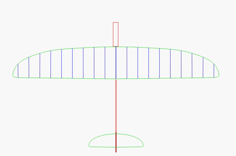
i had to scale the plan to figure chord lengths, but a 1:1 desk space to draw it would be great - the skills i have with lightburn can be used to simplify the rest of the workflow

thanks for instructions - it would be great to open a “recent project” template and get stuck in, but i want this possibility to not corrupt or lose the burning template for small things - essentially it would be like having 2 machines using the same interface, interchangeably

and i’d be even happier than i am already :smiley:

1 Like

This is an intriguing idea.

LightBurn curates feature suggestions on a Fider site (linked in Blue) on this line or linked Top Left on any Forum page.

Please sign up there and check to see if anyone else has suggested a similar Design set up. If you’re first, please post your suggestion and spell it out.

Now, with all that said, You can certainly draw and design Outside the work area on Layers that you don’t intend to engrave and you can turn off those layers when you’re wanting to send work to your engraver.

None of this should impact your settings for layers you intend to produce.

that’s exactly what i did, but the option for having a drafting area and a burning area set up as if i had 2 laser tables connected adds considerable flexibility in doing designing without faffing around switching things on and off

i know i can redefine area here

so here’s where i drew and then dragged components to scale so i could use the grid

i’d be just as pleased if i could draw a large scale grid (1mx300mm would suit my use) and leave the laser work area unmolested in normal scale to zoom in on as required for parts

the measuring tape tool means that if i know the chord of any rib in the planform, i can have the plotter within airfoil tools draw me a perfect sized pdf that will import as a smooth trace for cutting. including leaving appropriate “halo” for skins if desired - gold !

happy to offer the idea to your developers - the use of lasers is just taking off (boom tish!) for old school balsa builders like me, and the facility to create “short kits” of the parts that are most work by hand (cutting accurate ribs, doing lightening holes, whipping up perfect formers for known cross sections) is suddenly easy to undertake, and altering prototypes is easy with scaling, as is making angle guides and gussets with perfect accuracy

the value add of a simple 2d cad area for these people is a huge incentive to buy

i have already inspired a few fellow modellers over here, but the market for hobbyists (versus serious competition flyers) is poorly equipped for their particular niche

would be keen to participate in development as a service to the community - please let me know if there is someone there who is motivated; meantime i’ll offer the suggestion over at the site you linked

thanks for your input

2 Likes

As someone who just acquired a bunch of airfoil film and and an enormous amount of balsa from someone getting out of wing building, I’m very keen to do the same! Thanks for the links!

airfoil tools (hot linked above) is a wonderful free thing
you would also find these links useful, especially if gliders are your thing : Tailwind Gliders

some of the free plan sites also have cad files that work in lightburn

all in all, my use is a work in progress, but the signs are positive for it being a winning tool every bit as useful as a #11 blade and a razor plane for making things from balsa, but with its own niche application(s)

1 Like

i figured i can create a “big” work space by defining a “new device” and making it 1000mm x 500mm, and use it for drafting with the visual grid spacing at 10mm and move from my design area to burning area settings by simply selecting between design table and burn table choices

  • what i would request is some finesse in that the grid spacings be enhanced such that there are much darker lines at every 10cm, to facilitate my measurements
  • and when drawing straight lines horizontally or vertically, that there is a toggle button to “snap” them to be parallel to the x or y axis - that would be VERY useful - edit : scratch that request; per christian over in the request i made “Horizontal/vertical restraint is simply pressing shift while drawing”, so that problem is solved

both of these ideas i have suggested over at your link ( but one is redundant)

but in the meantime, apart from needing to copy and paste any parts i create in the plan view to a different file, i can do what i wanted reasonably effectively

even better workaround is to actually create a design area of 2000mm wide x 500mm tall, and then only use the right half of that area for design, effectively making 1000, 0 a surrogate 0, 0 to make lengths easier to drag in the x axis; then by pulling any parts to the corner starting at 0,0 (and within x<170mm and y<155mm space) and swapping to burn device, they are already in the available burn area and the saved file can be used to burn just the components presuming it obeys the flagged command to “ignore out of bound shapes if possible”

oh boy! this means a single file for design and burn, where the switching of device moves me between those options in the same window

so implementation of my requests essentially makes this already workable solution into an even better workable solution

bring it on !!! :heart_eyes:

edit : having just considered your “layers” toggle - that makes it easier again if i get used to using discrete colours for burning

i will attempt to stir up interest in my blog for the concept, once i do a lot of other tasks that should really take precedence… but the idea is refreshingly simple and already do-able, so i’m excited to spread the love

1 Like

This topic was automatically closed 30 days after the last reply. New replies are no longer allowed.