We’ve been using our 60x100 cm CO₂ laser for quite some time now. Recently, we added a second laser to support production, but this one has a smaller working area of 40x60 cm.
Is there a way to adjust the zero (0) reference point for our second, smaller laser?
Currently, I have to manually rearrange our designs to fit the smaller bed size.
Ideally, I’d like to set a fixed offset for the smaller machine (e.g., X: -30 mm and Y: -80 mm), so I can adjust the reference point precisely. This would allow us to use the same design files for both lasers without constantly modifying them.
Not an automated way to do this but you can select all and use the positioning numbers to place it exactly where you want it in relation to your home corner in a couple clicks.
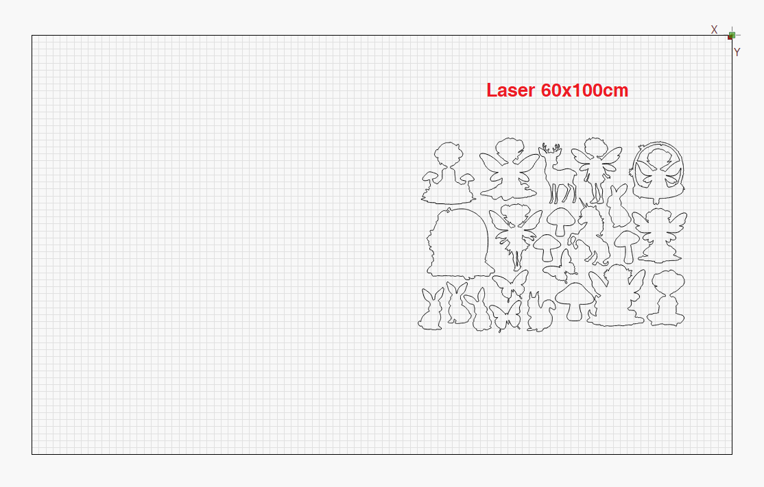
Before:
Probably not understanding you, but I set a user origin (Ruida console) and use that as a reference. You have to select user origin for the start from value.
If the origin in each machine is set for it’s size, then I’d think it should run…
Thanks for your help guys, however I’m still looking for a solution.
We use absolute coordinates for our programs and want to run the same file on two different laser bed sizes—the larger 60x100 cm and the smaller 40x60 cm. All of our designs fit within the smaller bed, so that’s not a problem.
The workflow is smooth once the file is set up for the large laser. But when we switch to the smaller machine, we have to manually rearrange the entire file to match the new origin, which is time-consuming.
What I’m looking for is a way to set a reference point offset after homing. If I could define, for example, an offset of X: -30 mm and Y: -80 mm on the smaller laser, I could align both machines to match the same coordinate system. That way, I wouldn’t need to edit the program each time—we could run the exact same file on both machines without adjustment.
I know this doesn’t answer your question. I don’t know of a way to get the desired result.
My question to you though is why don’t you locate your files on both machines at 0,0 or 10,10 or something reasonably close to that corner allowing for overscan? That way if it fits on the smaller bed it will certainly fit on the larger bed and there will be no further relocation needed.
With the same position from the home corner you could even move any jigs from machine to machine easily. You would need to install some type of fence for positioning, but I feel that is mandatory for absolute coordinates anyway.
I have a fence at 0-Y with an L at 650-X on a 700mm bed. That allows for simple positioning of my workpieces. I chose 650 because that side is closer to the laser and slightly more powerful than the 0 side.
Create a box around the cut’s and make it a tool layer. Group it altogether. Then you just need to use the Move to Right back corner. Ruida will ignore tool layer
If what you’re trying to do is run the same file on two different machines in absolute coords mode, then the absolute relative distance from the physical zero point of the machine will need to be the same.
Is there a reason you can’t use the same physical position of the material relative to the origin of both machnes?
Thank you for your response—I really appreciate it!
Yes, that’s exactly what I’m trying to achieve. The challenge is that the two machines are from different brands, so I’m unable to create a fixed fence or jig that ensures the material is placed in the exact same position relative to the origin on both machines.
Is there any way to set an offset to the homing point, or perhaps a workaround that would let me adjust the reference point after homing? That would make it much easier to run the same files without having to manually reposition everything.
The different brands don’t matter at all for a fence. The simple explenation is you attach a piece of plywood to the frame of the bed in a way that it wont be able to shift around. Having it stationary is vital. Then draw a line in Lightburn the full width of your bed with a 90* turn at the point of your choosing. I suggest at least 10mm to allow for overscanning if you engrave. If all you ever do is cut put the 90 at 0. Then use the laser to cut through the plywood on the line.
This gives you a fixed point to place your workpiece or any jigs you make against. The corner will always be at 10,0 (or whatever position you decide to have the fence) on either machine. This is much more accurate and faster than any placing by hand and eyeballing the location.
This shows my fence in place on my laser. Like I said previously I have mine set to 650,0 because I prefer to work closer to the left side. This is designed with a removeable jig insert and I also have one that sits at 700,0 (full width on my machine) and one that puts my rotary in the correct position. The interlocking system is not necessary, i just find it more convenient.
You can see the screws holding the jig in place along the back.