I recently built a Cantilever laser engraver. After a couple of comments from Mark at openbuilds about making it run vertical & adding a turntable, I was able to do both. I was trying to use the Z-axis for the rotary axis & initial testing worked in the rotary setup dialog, but could not get it to work when running a test burn. I enabled the Z-axis in the Device settings. Is there another setting I need to change? I was able to get it to work when switching it to the Y-axis. Also, it would be nice to have a feature of using either the X-axis or the Y-axis for the movements along the cylinder in rotary mode. I have to switch the cables on the controller board to get this to work. The cantilevered arm is normally my Y-axis.
I am using an Eleksmaker Mana 3 controller.
Files for this design are here: Horizontal Cantilever or Vertical Diode Laser Engraver by GeoDave - Thingiverse
Here is a short video of the first burn test in vertical configuration with turntable.
Cantilever Laser in Vertical Configuration test burn with turntable - YouTube
Using the Y axis for the scanning axis in rotary mode would be very rare, and would complicate the UI / configuration code considerably, so it’s not something we’re likely to add I’m afraid.
Using the Z axis for the rotary moves should work, but I honestly can’t say if that’s ever been tested. I know people have used Y and A, but I’m not aware of anyone using the Z. You would likely want to leave Z moves disabled for this, since the code generator might actually try to output two Z moves - one for the rotary and one for the ‘real’ Z axis.
I am able to get it to work well using the Z-axis. I initially set:
$102=200.000 ;Z-axis steps per millimeter
& 32 for the mm per rotation in LightBurn.
I got one full rotation, but rotational speed difference was considerable faster than the scanning axis. After doing a video of a dry run of a 100mm square, the speed came out to be 7.296x faster for rotation axis. So I recalculated the steps per mm based on that number, 200/7.296 = 27.412
Since I am using DRV8825 (200*32=6400) 6400/27.412 = 233.47mm.
I did a trial an error from this point adjusting only mm per rotation in LightBurn rotary setup, starting with 233 for that number. My final numbers give me 1 full rotation with rotary setup & speed between scanning axis & rotating axis is the same:
$102=27
243 mm per rotation.
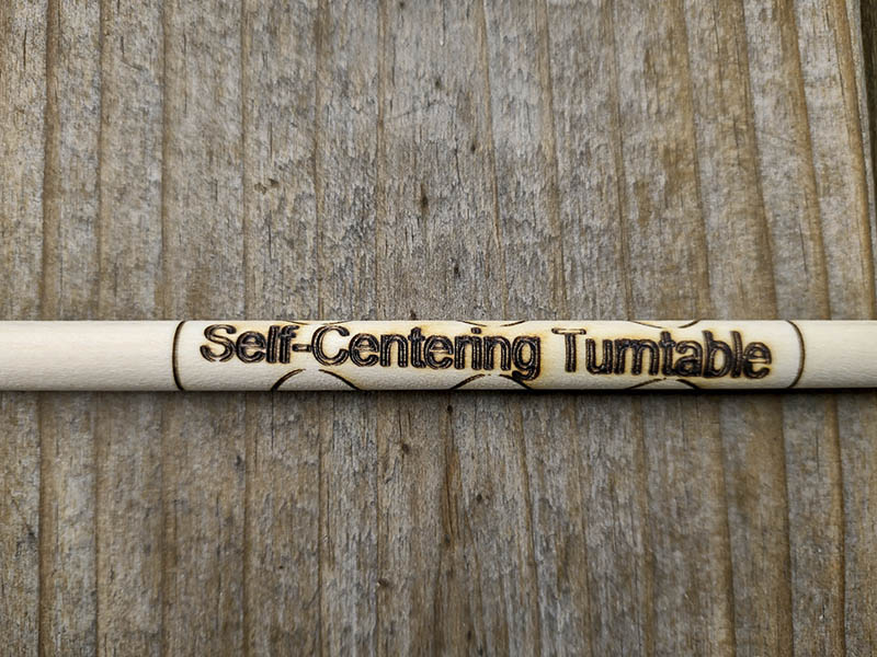
Here is a photo of test burn on a 3/8" birch dowel. It is slightly out of align with length of dowel, but I just needed to be more careful setting aligning this since it is a rather small object.
One minor comment bug with your software I noticed was it using Y instead of Z as shown in the 3rd line of this gcode output snippet, ; Bounds: X0 Y0 to X90 Y90 should be ; Bounds: X0 Z0 to X90 Z90.
; LightBurn 1.0.02
; GRBL device profile, current position
; Bounds: X0 Y0 to X90 Y90
G00 G17 G40 G21 G54
G91
M4
; Cut @ 600 mm/min, 80% power
M9
G0X18.725Z13.753
; Layer C00
G1X-0.778Z1.134S800F600
G1X-0.742Z1.189
G1X-0.705Z1.242
G1X-0.665Z1.294
G1X-0.625Z1.342
…
G1X0.044Z-1.763
M9
G1S0
M5
; return to starting pos
G0 X-89
This topic was automatically closed 30 days after the last reply. New replies are no longer allowed.