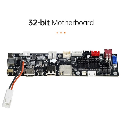
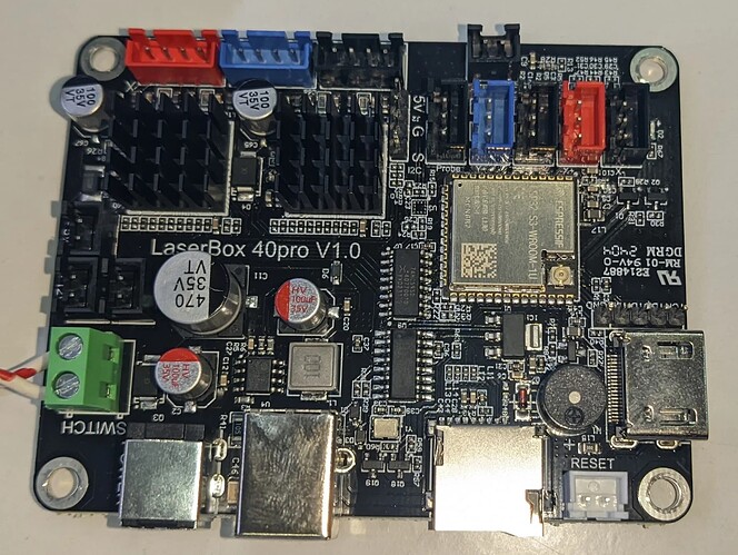
I found a msg on a German board of someone with the same problem, he has gone through the settings and came up with this, however after that he blew up the board.
Blockquote
#17
Also hier die Pinbelegung beider esp32
ESP32 ESP32-S3
GND GND
3V3 3V3
EN EN
IO36 IO4
IO39 IO5
IO34 IO6
IO35 IO7 LaserPWM?
IO32 IO15
IO33 IO16
IO25 IO17
IO26 IO18
IO27 IO8
IO14 IO19 scl
IO12 IO20
GND IO3
IO13 IO46 I2S_BCK
IO9 IO9
IO10 IO12
IO11 IO13
IO6 IO14 I2S_WS
IO7 IO21
IO8 IO47
IO15 IO48
IO2 IO45 I2S_data
IO0 IO0
IO4 IO35
IO16 IO36
IO17 IO37
IO5 IO38
IO18 IO39
IO19 IO40 sda
NC IO41
IO21 IO42
IO3 IO44 RXD0
IO1 IO43 TXD0
IO22 IO2
IO23 IO1
GND GND
Zusammenfassung für ES32-S3
Die I2S GPIO sind zu 99% sicher,
wurden von mir persönlich durchgeklingelt.
Laser GPIO sollte auch stimmen
I2S_BCK IO46
I2S_data IO45
I2S_WS IO14
LaserPWM? IO7
scl? IO19
sda? IO40
TXD0 IO43
RXD0 IO44
die angepasste yaml für FluidNC
board: XY LaserBox V1.0
name: ESP32-S3
meta: 2024-04-10 by AllEx
stepping:
engine: I2S_static
idle_ms: 250
pulse_us: 4
dir_delay_us: 0
disable_delay_us: 0
segments: 12
i2so:
bck_pin: gpio.46
data_pin: gpio.45
ws_pin: gpio.14
kinematics:
Cartesian:
axes:
shared_stepper_disable_pin: I2SO.0
shared_stepper_reset_pin: NO_PIN
x:
steps_per_mm: 80.000000
max_rate_mm_per_min: 1000.000000
acceleration_mm_per_sec2: 25.000000
max_travel_mm: 1000.000000
soft_limits: false
homing:
cycle: 0
allow_single_axis: true
positive_direction: true
mpos_mm: 0.000000
feed_mm_per_min: 50.000000
seek_mm_per_min: 200.000000
settle_ms: 250
seek_scaler: 1.100000
feed_scaler: 1.100000
motor0:
limit_neg_pin: NO_PIN
limit_pos_pin: NO_PIN
limit_all_pin: NO_PIN
hard_limits: false
pulloff_mm: 1.000000
standard_stepper:
step_pin: I2SO.1
direction_pin: I2SO.2:low
disable_pin: NO_PIN
y:
steps_per_mm: 80.000000
max_rate_mm_per_min: 1000.000000
acceleration_mm_per_sec2: 25.000000
max_travel_mm: 1000.000000
soft_limits: false
homing:
cycle: -1
allow_single_axis: true
positive_direction: true
mpos_mm: 0.000000
feed_mm_per_min: 50.000000
seek_mm_per_min: 200.000000
settle_ms: 250
seek_scaler: 1.100000
feed_scaler: 1.100000
motor0:
limit_neg_pin: NO_PIN
limit_pos_pin: NO_PIN
limit_all_pin: NO_PIN
hard_limits: false
pulloff_mm: 1.000000
standard_stepper:
step_pin: I2SO.5
direction_pin: I2SO.6
disable_pin: NO_PIN
control:
safety_door_pin: NO_PIN
reset_pin: NO_PIN
feed_hold_pin: NO_PIN
cycle_start_pin: NO_PIN
macro0_pin: NO_PIN
macro1_pin: NO_PIN
macro2_pin: NO_PIN
macro3_pin: NO_PIN
fault_pin: NO_PIN
estop_pin: NO_PIN
coolant:
flood_pin: NO_PIN
mist_pin: NO_PIN
delay_ms: 0
probe:
pin: NO_PIN
toolsetter_pin: NO_PIN
check_mode_start: true
macros:
startup_line0:
startup_line1:
macro0:
macro1:
macro2:
macro3:
after_homing:
after_reset:
after_unlock:
start:
must_home: false
deactivate_parking: false
check_limits: true
parking:
enable: false
axis: Z
target_mpos_mm: -5.000000
rate_mm_per_min: 800.000000
pullout_distance_mm: 5.000000
pullout_rate_mm_per_min: 250.000000
user_outputs:
analog0_pin: NO_PIN
analog1_pin: NO_PIN
analog2_pin: NO_PIN
analog3_pin: NO_PIN
analog0_hz: 5000
analog1_hz: 5000
analog2_hz: 5000
analog3_hz: 5000
digital0_pin: NO_PIN
digital1_pin: NO_PIN
digital2_pin: NO_PIN
digital3_pin: NO_PIN
digital4_pin: NO_PIN
digital5_pin: NO_PIN
digital6_pin: NO_PIN
digital7_pin: NO_PIN
NoSpindle:
arc_tolerance_mm: 0.002000
junction_deviation_mm: 0.010000
verbose_errors: false
report_inches: false
enable_parking_override_control: false
use_line_numbers: false
planner_blocks: 16
Anpassung der gpio.cpp /hab gerade gesehen das es da noch eine andere Zeile zur Anpassung der gpios direkt ,über dem von mir bearbeiteten block gibt.
struct pin_mux {
int pinnum;
const char* pinname;
const char* functions[6];
} pins = {
{ 0, “GPIO0”, { “GPIO0”, “CLK_OUT1”, “GPIO0”, “-”, “-”, “EMAC_TX_CLK” } },
{ 1, “GPIO1”, { “GPIO1”, “CLK_OUT3”, “GPIO1”, “-”, “-”, “EMAC_RXD2” } },
{ 2, “GPIO2”, { “GPIO2”, “HSPIWP”, “GPIO2”, “HS2_DATA0”, “SD_DATA0”, “-” } },
{ 3, “GPIO3”, { “GPIO3”, “CLK_OUT2”, “GPIO3”, “-”, “-”, “-” } },
{ 4, “GPIO4”, { “GPIO4”, “HSPIHD”, “GPIO4”, “HS2_DATA1”, “SD_DATA1”, “EMAC_TX_ER” } },
{ 5, “GPIO5”, { “GPIO5”, “VSPICS0”, “GPIO5”, “HS1_DATA6”, “-”, “EMAC_RX_CLK” } },
{ 6, “GPIO6”, { “GPIO6”, “SPICLK”, “GPIO6”, “HS1_CLK”, “U1CTS”, “-” } },
{ 7, “GPIO7”, { “GPIO07”, “SPIQ”, “GPIO7”, “HS1_DATA0”, “U2RTS”, “-” } },
{ 8, “GPIO8”, { “GPIO08”, “SPID”, “GPIO8”, “HS1_DATA1”, “U2CTS”, “-” } },
{ 9, “GPIO9”, { “GPIO09”, “SPIHD”, “GPIO9”, “HS1_DATA2”, “U1RXD”, “-” } },
{ 10, “GPI10”, { “GPIO10”, “SPIWP”, “GPIO10”, “HS1_DATA3”, “U1TXD”, “-” } },
{ 11, “GPIO11”, { “GPIO11”, “SPICS0”, “GPIO11”, “HS1_CMD”, “U1RTS”, “-” } },
{ 12, “GPIO12”, { “GPIO12”, “HSPIQ”, “GPIO12”, “HS2_DATA2”, “SD_DATA2”, “EMAC_TXD3” } },
{ 13, “GPIO13”, { “GPIO13”, “HSPID”, “GPIO13”, “HS2_DATA3”, “SD_DATA3”, “EMAC_RX_ER” } },
{ 14, “GPIO14”, { “GPIO14”, “HSPICLK”, “GPIO14”, “HS2_CLK”, “SD_CLK”, “EMAC_TXD2” } },
{ 15, “GPIO15”, { “GPIO15”, “HSPICS0”, “GPIO15”, “HS2_CMD”, “SD_CMD”, “EMAC_RXD3” } },
{ 16, “GPIO16”, { “GPIO16”, “-”, “GPIO16”, “HS1_DATA4”, “U2RXD”, “EMAC_CLK_OUT1” } },
{ 17, “GPIO17”, { “GPIO17”, “-”, “GPIO17”, “HS1_DATA5”, “U2TXD”, “EMAC_CLK_1801” } },
{ 18, “GPIO18”, { “GPIO18”, “VSPICLK”, “GPIO18”, “HS1_DATA7”, “-”, “-” } },
{ 19, “USB_D+”, { “USB_D+”, “VSPIQ”, “GPIO19”, “U0CTS”, “-”, “EMAC_TXD0” } },
{ 19, “USB_D-”, { “USB_D-”, “VSPIQ”, “GPIO20”, “U0CTS”, “-”, “EMAC_TXD0” } },
{ 21, “GPIO21”, { “GPIO21”, “VSPIHD”, “GPIO21”, “-”, “-”, “EMAC_TX_EN” } },
{ 22, “GPIO22”, { “GPIO22”, “VSPIWP”, “GPIO22”, “U0RTS”, “-”, “EMAC_TXD1” } },
{ 23, “GPIO23”, { “GPIO23”, “VSPID”, “GPIO23”, “HS1_STROBE”, “-”, “-” } },
{ 25, “GPIO25”, { “GPIO25”, “-”, “GPIO25”, “-”, “-”, “EMAC_RXD0” } },
{ 26, “SPICS1”, { “SPICS1”, “-”, “GPIO26”, “-”, “-”, “EMAC_RXD1” } },
{ 27, “SPIHD”, { “SPIHD”, “-”, “GPIO27”, “-”, “-”, “EMAC_RX_DV” } },
{ 28, “SPIWP”, { “SPIWP”, “-”, “GPIO28”, “-”, “-”, “EMAC_RX_DV” } },
{ 29, “SPICS0”, { “SPICS0”, “-”, “GPIO29”, “-”, “-”, “EMAC_RX_DV” } },
{ 30, “SPICLK”, { “SPICLK”, “-”, “GPIO30”, “-”, “-”, “EMAC_RX_DV” } },
{ 31, “SPIQ”, { “SPIQ”, “-”, “GPIO31”, “-”, “-”, “EMAC_RX_DV” } },
{ 32, “SPID”, { “SPID”, “-”, “GPIO32”, “-”, “-”, “-” } },
{ 33, “GPIO33”, { “GPIO33”, “-”, “GPIO33”, “-”, “-”, “-” } },
{ 34, “GPIO34”, { “GPIO34”, “-”, “GPIO34”, “-”, “-”, “-” } },
{ 35, “GPIO35”, { “GPIO35”, “-”, “GPIO35”, “-”, “-”, “-” } },
{ 36, “GPIO36”, { “GPIO36”, “-”, “GPIO36”, “-”, “-”, “-” } },
{ 37, “GPIO37”, { “GPIO37”, “-”, “GPIO37”, “-”, “-”, “-” } },
{ 38, “GPIO38”, { “GPIO38”, “-”, “GPIO38”, “-”, “-”, “-” } },
{ 39, “MTCK”, { “MTCK”, “-”, “GPIO39”, “-”, “-”, “-” } },
{ 40, “MTDO”, { “MTDO”, “-”, “GPIO40”, “-”, “-”, “-” } },
{ 41, “MTDI”, { “MTDI”, “-”, “GPIO41”, “-”, “-”, “-” } },
{ 42, “MTMS”, { “MTMS”, “-”, “GPIO42”, “-”, “-”, “-” } },
{ 43, “GPIO43”, { “GPIO43”, “-”, “GPIO43”, “-”, “-”, “-” } },
{ 44, “GPIO44”, { “GPIO44”, “-”, “GPIO44”, “-”, “-”, “-” } },
{ 45, “GPIO45”, { “GPIO45”, “-”, “GPIO45”, “-”, “-”, “-” } },
{ 46, “GPIO46”, { “GPIO46”, “-”, “GPIO46”, “-”, “-”, “-” } },
{ 47, “GPIO47”, { “GPIO47”, “-”, “GPIO47”, “-”, “-”, “-” } },
{ 48, “GPIO48”, { “GPIO48”, “-”, “GPIO48”, “-”, “-”, “-” } },
{ -1, “”, { “” } },
};
Anpassung GPIOPinDetail.cpp
namespace Pins {
std::vector GPIOPinDetail::_claimed(nGPIOPins, false);
PinCapabilities GPIOPinDetail::GetDefaultCapabilities(pinnum_t index) {
// See https://randomnerdtutorials.co…2-pinout-reference-gpios/ for an overview:
switch (index) {
case 0: // Outputs PWM signal at boot
return PinCapabilities::Native | PinCapabilities::Input | PinCapabilities::Output | PinCapabilities::PullUp |
PinCapabilities::PullDown | PinCapabilities::ADC | PinCapabilities::PWM | PinCapabilities::ISR |
PinCapabilities::UART;
case 1:
case 2: // Normal pins
case 4:
case 5:
case 6:
case 7:
case 8:
case 9:
case 10:
case 11:
case 12:
case 13:
case 14:
case 15:
case 16:
case 17:
case 18:
case 21:
case 36:
case 37:
case 38:
return PinCapabilities::Native | PinCapabilities::Input | PinCapabilities::Output | PinCapabilities::PullUp |
PinCapabilities::PullDown | PinCapabilities::ADC | PinCapabilities::PWM | PinCapabilities::ISR |
PinCapabilities::UART;
case 26: // SPI flash integrated
case 27:
case 28:
case 29:
case 30:
case 31:
case 32:
return PinCapabilities::Reserved;
default: // Not mapped to actual GPIO pins
return PinCapabilities::None;
case 43: // TX pin of Serial0. Note that Serial0 also runs through the Pins framework!
return PinCapabilities::Native | PinCapabilities::Output | PinCapabilities::Input | PinCapabilities::UART;
case 44: // RX pin of Serial0. Note that Serial0 also runs through the Pins framework!
return PinCapabilities::Native | PinCapabilities::Output | PinCapabilities::Input | PinCapabilities::ISR |
PinCapabilities::UART;
}
}
Ich hoffe das kann irgendjemanden helfen**


