I have a Vevor L4681 machine. I guess it comes with a controller from VigoTec, which offers Wifi and USB connection.
The machine runs fine with VivoWorks and LaserGRBL - I get no problems at all.
But with Lightburn 1.3 (testversion) I have issues.
The machine indeed has been found when searching for devices (mostly as GRBL, Lightburn sometimes finds it as iLaser). Anyway, when the device is found and connected as GRBL, I get a conenction message in the Lightburn console
(“Auf Verbindung warten…
ok
[VER:]
[OPT:V,15,511]
Target buffer size found
ok”)
And with $$ in the console I do get the parameter lists from the controller.
But as soon as I try to just move the laser around via the arrow buttons or start a laser job, it hangs.
Example for moving the laser to the right:
(“<Idle|MPos:0.000,0.000,0.000|FS:0,0|WCO:0.000,0.000,0.000>
ok
Stream wird gestartet”)
Really nobody with an idea how to solve these problems?
I thought (because the basic communication with the controller seems ok) the problem is the way some code is sent to the machine or maybe the code itself.
I thought that if $$ at least gave me the controller parameters there could be a way to identify the communication problems when sending jobs to the machine or move the laser to a position.
I tried, but to no avail. I enabled the DTR-signal for my device (which is configured as straight GRBL device at COM4).
Then I simply tried to move the laser with the Lightburn arrow buttons… nothing happened.
This is an excerpt from my console logging output from the help menu:
(I did press STOP after about 20 seconds of nothing happening and quit Lightburn for the log file to be written)
Afaik the controller has an esp and an STM32 onboard (I don’t know if that’s an important information for my problem) It is capable of communicating through WiFi and USB. But I only use the USB connection and the device indeed works flawlessly within VigoWorks and LaserGRBL. If only I could get this to work with Lightburn because it seems a lot easier to do design for lasering with Lightburn.
I tried 57600 with synchronous and buffered mode and with DTR enabled and disabled. No matter what my settings were - the laser didn’t move a millimeter.
I just checked my LaserGRBL settings. The machine has no problems working with 115.200 baud and buffered streaming mode.
My CH340/341 driver came with the machine software that I downloaded from vevorengraver.com
I tried another one from www.wch.cn and I even tried the driver install option from LaserGRBL. With all drivers I get the same problem within Lightburn.
I assume that my machine from Vevor indeed comes from VigoTec. Maybe this is a clue because they produce those WiFi/USB combi controllers (an earlier version of these controllers comes with the VigoTec VG-L7X - at least I read this info on the LaserGRBL site). LaserGRBL has been altered to cope with this controller. See Laser Vigotec VG-L7x WiFi LaserGRBL issue · Issue #1123 · arkypita/LaserGRBL · GitHub for infos on this.
It seems this controller handles the g-code a little bit different than standard GRBL does (my guess). Maybe it has something to do with the combination of ESP32 and STM32 on these controllers, and the author of LaserGRBL has put quite an effort to solve this problem.
For the VG-L7X there is a hardware hack to bypass the WiFi chip and directly get the rx/tx signals to the AT328. My board has an altered design (I think) in using an STM32. Therefore I’m unable to try the hack myself (it’s just soldering two wires and remove four resistors). But LaserGRBL can communicate with my machine and I just tested a new engraving job with LaserGRBL about an hour ago. No problems at all.
(just to make sure that the machine is working under LaserGRBL flawlessly - my aim still is working with Lightburn).
Yes, I did see this when I stumbled over the hardware hack. Sadly, I couldn’t find any option to get my controller to boot mode, which I think is neccessary to flash the firmware onto the controller.
Every effort I tried (Arduino IDE, xloader, LaserGRBL, even the built-in update option in VigoWorks) went nowhere. There’s no documentation available to get this controller to accept and flash any firmware, be it in hex or bin format.
With the VigoTec VG-L7X controller you have to press and hold the power button while pressong the third button (on the right side) just shortly. Holding the power button should pull the appropriate pin to a state where the controller accepts the flashing of a firmware.
I tried it that way - my controller seems laugh at me and does nothing in terms of flashing a firmware.
Sadly, I couldn’t find the appropriate points on my controller board to use the hardware hack.
I couldn’t find the correct resistors to be cut and the points to which the wires had to be soldered.
My board uses an STM32 whereas the VG-L7X board has an ATMega328, and so the pin and board layout is different.
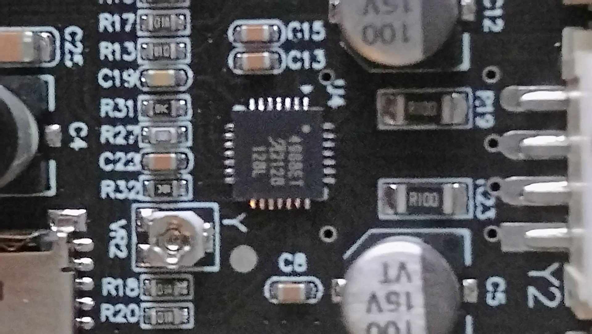
I’m sorry, my mobile is a bit outdated concerning the camera.
Do you think these photos provide enough information?
Maybe it’s possible to recognize the four solder points for the two cables of the hardware hack (which might solve the problem)?
Afaik the hack seems to bypass the encryption and sends incoming g-code from the usb port directly to the controller chip (which in my case is an STM32, I think).
From what I can tell the hack basically bypasses the ESP32 entirely. So the USB connection goes from WCH340 directly to Atmega328p. So basically USB->Serial->Atmega.
I’m reviewing the datasheet for “STM32G030C8”. Hopefully I’ve read the chip model correctly.
Looks like the STM32 offers 2 different USART interfaces. USART1 provides more capabilities than USART2 but not sure otherwise how they’re different.
TX/RX pins are PA9/PA10 (USART1) or PA2/PA3 (USART2) respectively.
The problem is solved - twice indeed. I bought a DLC32 controller board with appropriate drivers (TMC 2208) which work smart with Lightburn (I had to switch two cables from the laser connector).
And (!) the manufacturer did send me another controller board which looks the same as my original controller (the one that came with the machine). This new controller also seems to do the job as well.