Hi
A while ago I purchased a Vevor 3018 CNC/Laser machine.
I would like to install limit switches on it.
They are all actually installed now, but I am having difficulty getting them to work.
When I test the voltage output at the X/Y/Z limit pins on the motherboard, it gives me a reading of 3.27 volts.
Can anybody confirm that this is the normal voltage for the pins, or should it be higher?
Thank you
They are input pins, not output pins… the controller reads these…
If you are reading from ground, I’d expect 5V, so maybe you have a different controller…
In either case these work the same… if it’s grbl it should work as follows.
I have a similar if not identical machine out in my shed, it came with home switches. Most of these little boards use a wired or operation using switches that pull the input of the controller low.
If they are NO, then they pull the input low when active… NC is opposite…
It should work correctly as configured, I believe. You will have to confirm this…
Are these NO or NC switches… where did you get the information on how to do this?
These are from an old grbl handout I have this information for $5 and you will have to enable homing using $22 to enable the Homing Cycle.
Requires limit switches be installed. Enabling this will lock out all gCode commands until
(Enable/Disable) a “Homing” cycle is run.
and $5 is defined as
This refers to the limit switch pins which by default are set to high using the Arduino’s
internal pull up resistors. Grounding the pin tells GRBL the limit switch is tripped. For the
opposite behavior use the setting $5=1 which tells the system that a high is the limit
switch trigger. You must also install external pull down resistor with the $5=1 setting.
I don’t know what controller is in yours, one of mine, has the X, Y and Z in Chinese notation Z, Y and X. The silk screened board markings are incorrect…
What I’m trying to say, I don’t know enough about your setup and how you did it to really help you…
If we can’t figure this out quickly, I’ll lug mine in here, check the controller type and see how it works and is configured…
![]()
Thanks for your reply Jack
I have tried setting them up as both NO and NC; neither works, although the NC (seems to be) is the preferred way to set up the switches
I did change the grbl settings as you suggested.
I made up a hand held switch that would actuate the limits and tested it from that as well … still no joy.
I am inclined to think the board is faulty, especially as I am only getting 3.27 volts at the inputs.
I have phoned Vevor for some information, but so far they have not replied.
Do you have a link to your machine?
If it’s the same as mine, I’ll drag mine out tomorrow and have a look see…
![]()
Thanks Jack
this one, but with a small laser as well.
It appears that we have different controllers… Mine doesn’t have the same connector pattern… I was suspicious that the 3.3V you were reading is because of a 3.3V cpu. Mine is 5V. It would also tend to indicate the default is pull down…
All of the videos (I could sit through) wired these up as a pull down for active. This is safer from the standpoint, that a pull down works at any voltage. When the switch closes it complete the ground.
The danger of using a pull up and maybe your problem is that if you pull a cpu’s input up to 5V and it’s only rated at 3.3V, you might have damaged those inputs…
You’re just used to positive logic, if it’s high it’s on… Pull downs is pretty common on most of these and all the US built machines I’ve ever been around… For the US machines, I know they did it to keep the noise problems at a minimum and to save money… they only needed one wire and used the frame as a return path.
They work basically the same either way…
I have mine out, but haven’t powered it up. The boards have three lines, power, signal and ground, but I think the power is for the onboard led only… I’ll check this later…
If neither works how can you say it’s the preferred way?
How did you set this up this way? Configuration or changing the wiring or ?
I’d suspect they are pull down…
- How was the machine originally configured as far as active state?
- Did you do this off the top of your head, or did you follow some installation video or procedure?
- Did you pull those 3.3V inputs up to 5V?
![]()
I say NO, because I probably watched the same videos as you did. ![]()
- I really cannot remember what state the machine was originally in, but I followed the instructions and changed the GRBL settings before using (connecting) the switches.
- As above. Even so, it isn’t that difficult to understand, it’s just that it won’t effingwell work!
- How could I pull them up to 5v? I only know how to open and close the switches and connect them to the labelled inputs. A method for doing this totally eludes me.
I would have difficulty using single signal wires as half the frame is some sort of plastic that wouldn’t conduct from the side aluminium framework.
What instructions ?…
I know you know, but I’m clueless …
That’s one of the things I keep trying to get out of you… some are good, some not so good… So I have no idea of what is wired to what…
A procedure along with any wiring diagrams you followed would help me look at what you have… a link would be nice.
![]()
I used various sources.
I downloaded and read the GRBL manual. (I just skimmed a lot of it that wasn’t relevant.)
I also watched a couple of YouTube videos.


https://www.reddit.com/r/hobbycnc/comments/o92aw7/help_with_3018_cnc_limit_switch_wiring/
I searched for a link to the Vevor manual but I couldn’t find one.
And although this manual (This link downloads a PDF)
https://www.google.com/url?sa=t&rct=j&q=&esrc=s&source=web&cd=&ved=2ahUKEwjYx5SxvqaAAxUCplYBHeR1AcIQFnoECBAQAQ&url=https%3A%2F%2Fs3.amazonaws.com%2Fs3.image.smart%2Fdownload%2F101-60-280PRO%2FGenmitsu_3018_PRO_User_Manual_V1.1%2520_%2520202009.pdf&usg=AOvVaw3kilo8gOMWShXx2ecc7Vhx&opi=89978449
Is not exactly the same, it is pretty close.
This leads me to the controller being a camxtool v3.* I downloaded the manual on the board and confirmed part of what we’ve stated… You should save this manual pdf in case you need it.
They knew this on my 2.4 board, sadly it’s still wrong…
The Reddit article is typical, bad information…
On this board, you need to use NO switches wired across the limit inputs… When the switch closes, it shorts the two pins pulling them low… one side is ground so it pulls the other pin low…
The schematic does not have a 3.3V output, so I have to assume that voltage you are reading is indicative of a problem.
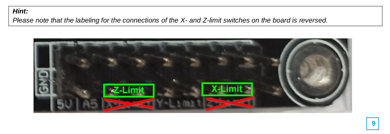
My red mark is pointing at the ground pin… these are ground all the way across the bottom row of pins.
The green mark is the pair of inputs for the Y home/limit. Which you use is irrelevant.

This is the same chip that’s on an Arduino… 328p… they have internal pull up resistors that can be enabled via software…
Check the voltage between where the red ground mark is and the pin above it… You should get 5V. Unplug your switches and check from the ground pin to it’s input… all axes limits should also read 5V.
If these voltages read ok with the switches removed… then…
- is that you have the hardware connected correctly.
- Can you take a photo or give me a link to the switches you’re using and how you wired them?
- They should be wired so they make a connection when activated. These are NO.
Good luck
![]()
Thanks for all your help Jack.
With all the switches removed and the machine just waiting for a command from the computer, the ground to all the other pins (not the ground ones :)) read 3.27 volts. When I am moving an axis and I then close the switch, the machine keeps going, but when I release the switch it stops and will not start again without a reset.
Still, at least I can now get it to stop; but only by closing and then releasing the limit switches by hand.
Maybe this extra information will help you, maybe not. I feel like leaving it all for a year until the frustration goes away.
PS Most of the sites I have looked at have recommended that the switches be NC, and that way, if the power fails or the circuit fails then it will be broken and it should shut down.
The boot sequence moves the head to it’s sensor, when that becomes active the machine stops and backs up a predetermined amount then re-engages the switch a a lower speed for more accuracy. All of these are defined within the controller… These, along with the mS of debounce delay are stored within the controller.
Some of these registers hold information like the speed of the home function and the speed of the re-engage speeds. Direction to travel to home, and if enabled to detect soft errors the work area size. All of these exist in the controller.
So to get it to home, manually, you have to active each switch twice… If it’s configured for hard limits, it will fault if you activate it too many times.
The voltage is not what I expect from one of these, but it appears to be reading the switch since it will halt when you activate it…
Sounds like your board is one of the 3.3v chips… the schematic I thought was yours show a 328p processor. This will run at 3.3V but the schematic shows no 3.3V supply line…
We’ll assume this isn’t part of the issue.
Does the console in Lightburn have a complaint from the controller? Like a limit fail or home fail error? Here is a list of error code, especially the alarm and error codes.
For your description to have more meaning an error message would be great… along with what state the machine is in when it faults.
Here is saint smart list of gcode… note of the non-gcode options for examining what’s going on with the machine…
Good luck
![]()
This topic was automatically closed 30 days after the last reply. New replies are no longer allowed.