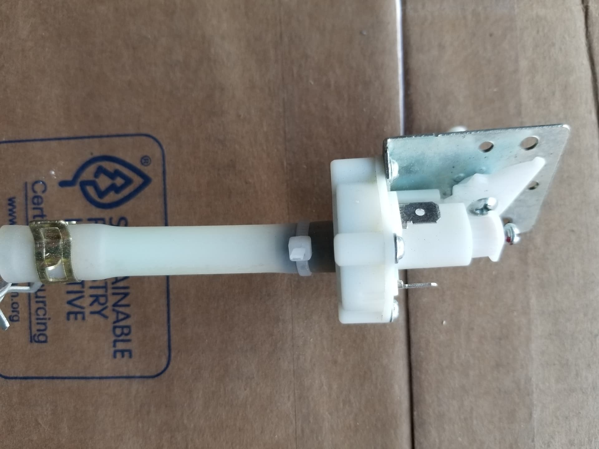
I have a 60 watt chinese laser blue/grey cabinet. A while back the water hose broke at the nipple of the solenoid and I was flooded. The solenoid has a plastic body, one water line and 2 wires. The solenoid looks like a simple spring loaded device. When the water line broke there was enough of the nipple left that I could get a small ss hose clamp (worm screw type) attached; it took quite a bit of torque to get a secure fit. Now it appears that the plastic housing of the solenoid has cracked and I have a constant drip.
Can I bypass the solenoid by connecting the two wires together? OR Can I disconnect the water hose, mechanically force the solenoid open and make it believe the water pressure is there? OR is there a 3rd option?
I do have a WATER CHILLER (really just a simple radiator) and it has it’s own sensor and alarm.
I am mechanically sufficient but when it comes to electronics an absolute zero.
Water is ‘active’ if the WP1 signal is pulled to ground meaning you have coolant flow. My machines two wires went to WP1 and GND.
If this is the case, you can wire up your 3000 series chiller to the machine quite simply…
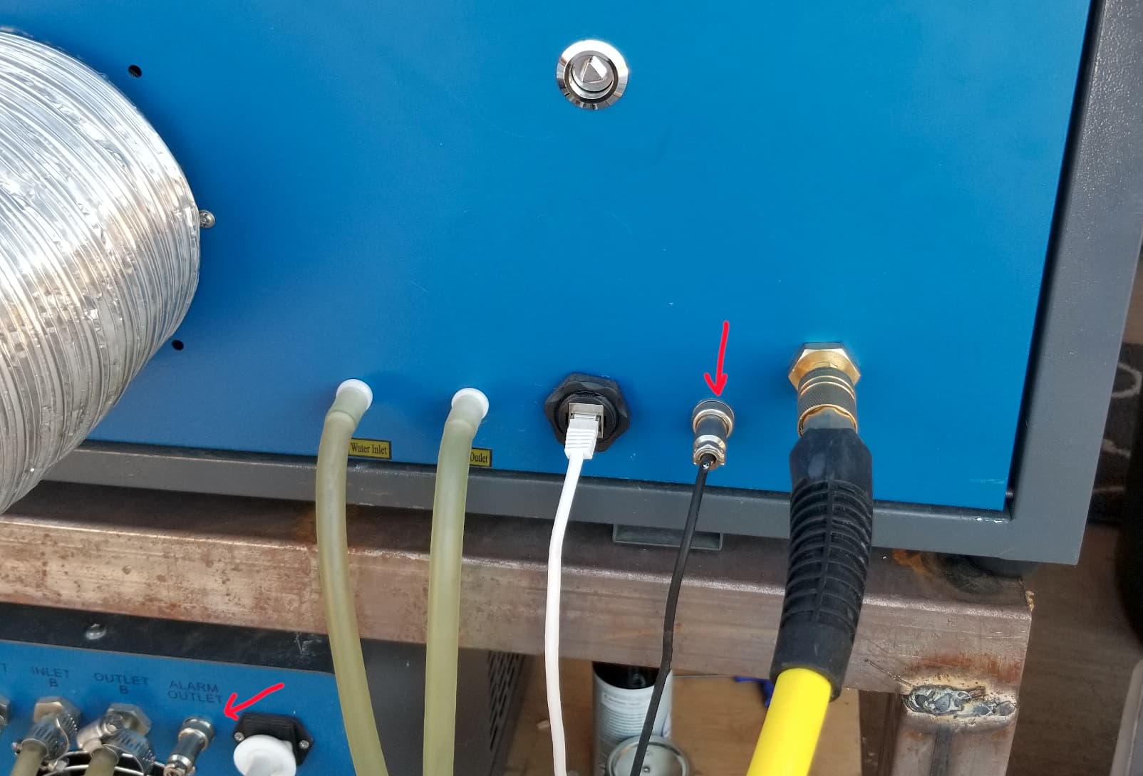
I put in a connector and used the wires that were there for the sensor and wired them to the connector. #4 in the photo. At the very bottom of the photo is the top of my chiller. You can see the connection to the ‘alarm outlet’ of the chiller… Both ends have red arrows…
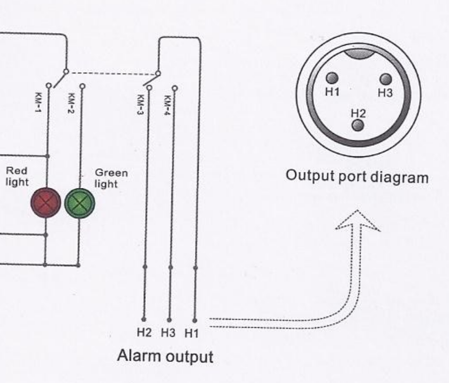
When it’s running properly and the status is ‘green light’, it’s relay is picked and H1 is connected to H3. If you put use these two lines and connect them to your ‘sensors’ lines, I think it will work fine.
Can you hear me singing?
I mentioned I have no clue about electronics and I am not kidding. Thanks in advance for holding my hand thru this issue.
Pressure switch is spot on. Are the wire terminals marked as to which is ground and WP1? If not, how do I tell which is which?
When it comes to the pin connector:
WP1 connects to which output port, H1, H2 or H3?
GND connects to which output port?
Most confusing, what is the 3rd wire?
Have a good chuckle on me.
Thanks for the help.
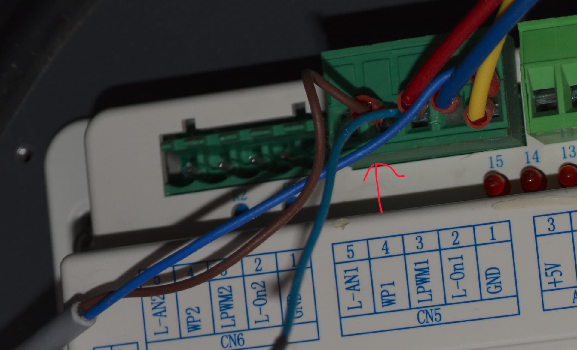
The simple way… usually there are two colors coming from the sensor… Look at the controllers input of WP1 and see what color is wired to it… the other is ground… It’s the gray cable at the bottom.
Mine has a blue and brown lead, you can see the brown wire → WP1 the blue → GND.
All of these are insulated from ground, you just want to connect to H1 and H3. That will complete the circuit for WP1 and tell the Ruida that your coolant is flowing. Doesn’t matter which is which since all of the H terminals are insulated from ground.
I don’t know, so you need to find the end and see where it goes. If you look at my photo, the gray cable is going to the switch. It only has two wires. Sometimes they end up with three, for various reasons but the Ruida WP control only needs two.
Were all three wires connected to something on the original sensor?
On the 3 pin connector . . . I run a wire from WP1 to H1 and a wire from H3 to H3?
What do I do with the ground wire? Attach to cabinet?
Sorry for the confusion but there is no 3rd wire, I was looking at the 3rd post on the pin connector and wondered what it was for. Just assumed a 3rd wire was involved.
No problem… stay relaxed it isn’t rocket science you are doing fine…
Let me explain a little bit here..
With the original sensor, which has two wires. One of them goes to ground (at the controller) and one of them goes to the WP1 input of the Ruida. If you look back at the photo of the controller, the blue wire goes around and is connected to CN5 pin 1, which is ground.
When the sensor becomes ‘active’ or sensing pressure, it ‘closes’ the switch or in simple terms ‘shorts’ out the two wires.
This ‘grounds’ the WP1 input, signalling the controller that the circuit is active or functionally OK.. you have coolant flow.
I used the original wire that went to the original sensor, one to H1 and the other to H3.
In the chiller, this is a relay, so these connections are isolated from the machine..
It’s easy to get these types of plugs wired incorrectly because they usually show you from the front and you have to work on the back, so take the time to ensure it’s ok. Worst case it will show OK when the chiller isn’t running…