What are the four set screws at the end of the emitter for?

Forgive the potential noob question but I cant seem to find any details on what the four set screws around the end of the emitter are for. My old tube never had these. Assuming some kind of alignment?

image

It is correct. The 4 screws are used in the factory to fine tune your first lens which is at the end of the tube. You need to be very sure of what you are doing before tinkering with these screws

So there’s actually a lens in the emitter? I thought one end was a fully reflective mirror and the other was a partially reflective mirror to increase the intensity of the beam until it passes through the emitter end mirror. Anyone have any good resources for learning more about tube construction and performance?

What you say is probably more accurate, but it is an optical element to capture and direct the beam itself.

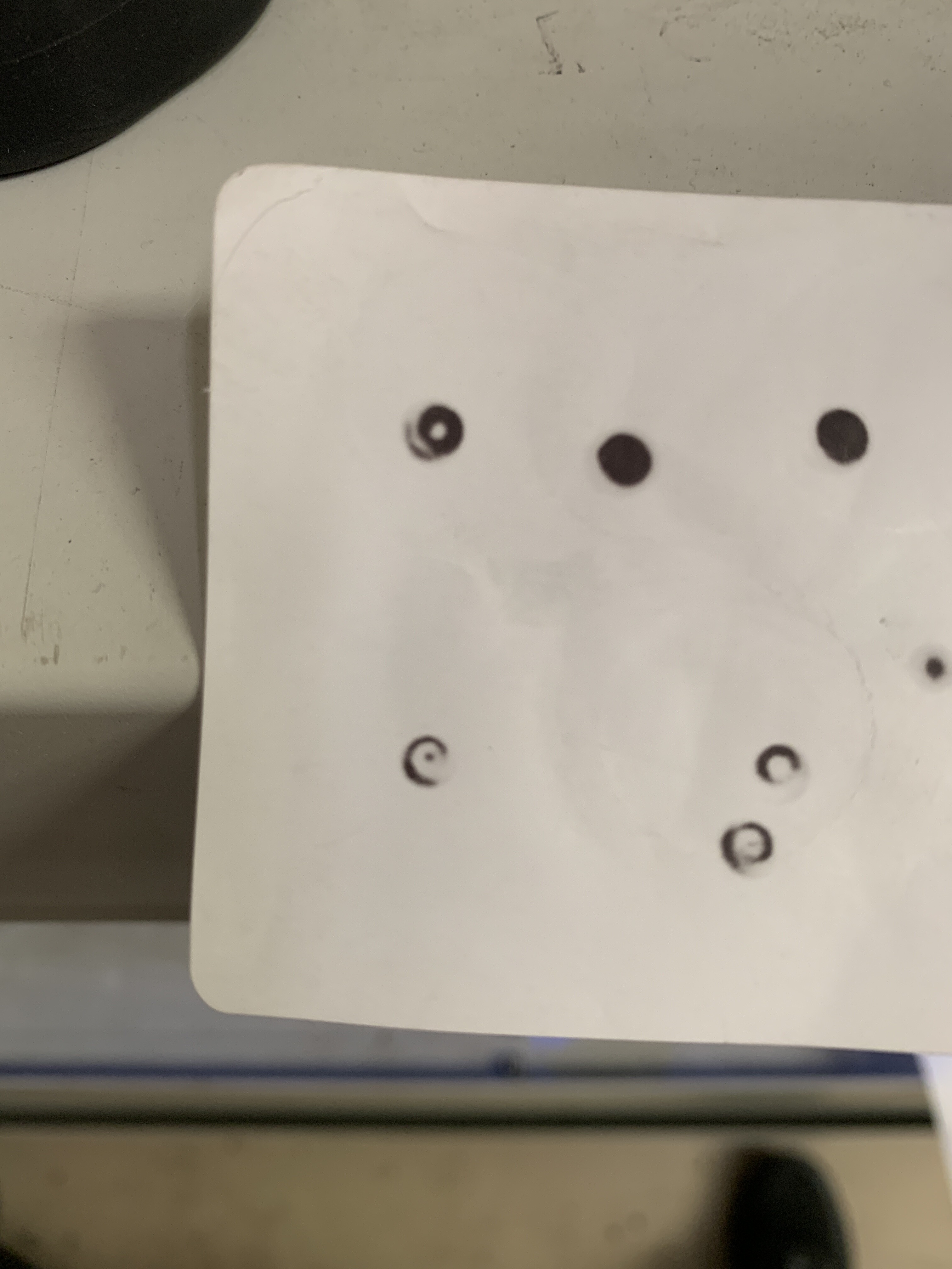
Are there any indicators that might point to the need for these to be adjusted? I ask because I’m getting an odd beam pattern when I’m pulsing at low power closest to the emitter. I’m not sure if this is common or not. If you look at the attached image you can see what I’m talking about. When within 50cm of the emitter end or so I get a crescent or “O” shaped beam but it moves to a more defined point as pulse farther away… say 70cm + from the end of the emitter. I use thermal paper and set my max power to 11% to pulse. This is for a 168cm tube rated 130w continuous 170w peak.

No! Those set the front mirror alignment and if misadjusted your laser will quit working. I highly recommend you don’t mess with them.

Ok, good to know. Thank you.

It’s my understanding that there are mirrors at each end of the tube, one fully reflective and one partially, the screws are the manufacturer’s way of adjusting the mirrors to align the laser beam during the manufacture process. Once set they should never require adjusting.

There are plenty of books on Laser Technology out there, the library may be able to order them when they reopen or eBay have lots currently available.

I’m not sure what lens your using or what you’re trying to achieve taking a beam pattern 50 of 70 cm from the emitter? What pattern are you getting from the lens when it’s focussed on the thermal paper?

To me it looks very nice, no sign of more spots or anything in that direction.

What I’m trying to achieve is a consistent cut and what I’m experiencing is almost too much power on the bed corner closest to the emitter. Is there a working distance spec from the end of the tube where cutting is optimal? If you look at the attached photo you’ll see what I mean. I’ve spent hours checking alignment and checking again. My bed is dead flat. This is the same focal distance same laser power but the kerf and penetration of cut is SUBSTANTIALLY greater. Notice how I get a nice clean hairline on bottom right. Furthest from the bed, razor sharp focus. As I move closer to the emitter (top left) my kerf is about 5x in thickness. (0.5mm vs 0.1mm) No matter what I do up in that corner I can’t seem to effect the cut thickness. I’ve tried refocusing in just that corner and I cant get the beam to focus nearly as cleanly. Again after the beam has travelled about 70cm or so it seems to “tighten up” I just can’t figure out what I’m missing. I know power will always be more intense the closer you are to the emitter but I should still be able to focus it no? The reason I’m exploring the beam pattern stuff is it almost feels like the tube is emitting a thicker beam right at the emitter? I can’t think of what else would contribute to a thicker kerf like that.

It is not so long ago that there was a post here with the same problem, it still ended up being a setting problem of the mirrors, the lens and the bed. (I read that you did it all)

Maybe I’m missing something on my alignment. but it all looks correct. I ordered the reverse laser tool from American Photonics to see if that reveals anything I missed.

just a little curiosity, it took me weeks to find out that my cable duct was just a little bit too tight and could lift the entire nozzle head rear 0.2mm, at the end furthest away from the mount.

1 Like

Have you done Russ Sadler’s “anal thermometer” test at all four corners plus the center of the bed to see if your beam stays centered/vertically aligned straight up and down from the top of the laser head down through the nozzle? If your beam is coming out at more of an angle in the upper corner, it could be the source of your problem. This test revealed an alignment issue I have been chasing for quite a while. Here is a test example created a while back. You can see the issue. I have been able to correct things some, but even now, it still isn’t perfect.

Nozzle Test Small

1 Like

No I haven’t I’ll look that up. Thanks!

Here is the tool I used. I believe someone else created it (maybe Gene U.?) and then I modified the hole size to better fit my laser’s nozzle. No doubt you will need to modify the hole size to snuggly fit your laser’s nozzle tip. You have to be very careful to center the nozzle exactly for each test fire. Turn your air assist down very low. Also, make sure the tool is held level front to back as well as size to side. If you purposely do a non-level test fire, you will see how the results can be inaccurate.

Anal Thermometer Laser Testing Adjusting Centering Tool 5 Hole.lbrn (20.1 KB)

Thanks! Is there a writeup on proper use of the tool somewhere?

Not really. You can search for and watch Russ Sadler’s (Sarbar Media) Youtube video detailing why and how he used it. I don’t know the video number. I am guessing it was within his first 50 videos.

1 Like

Ok, I’ll look that up, thanks. Not quite following how that thermometer is used just from looking at it, guessing the video will make it clear.

Neat little tool but looks pretty spot on to me. Checked square with the bed in all directions too. I’m really at a loss here, it really feels like the beam just doesn’t focus as well up at that top point for some reason I still can’t pin down.