I have been working to draw a compass rose geometric design. I’m using snap to grid and everything looks pretty good until I use max zoom to look at the points that join. The lines I draw do not sit on the grid precisely. I go into node editing and move the lines to join on the grid precisely. After a while I recheck and again the lines are not on the grid. If I rotate the design 180 I’m no longer on the grid. At max zoom I can measure a delta in the 10 thousands range. I KNOW that is way more precision than is required for my project and more than my laser can deliver, but just wondering why snap-to-grid is not more precise.


My system is in mm but the values are roughly the same as yours anyway. But I don’t experience the problems you describe or can’t reproduce them. If I draw a square, insert nodes in the center points of the lengths and drag them to the center, I can mirror, flip or rotate them without the result changing. Can you post an example (.lbrn2) here?
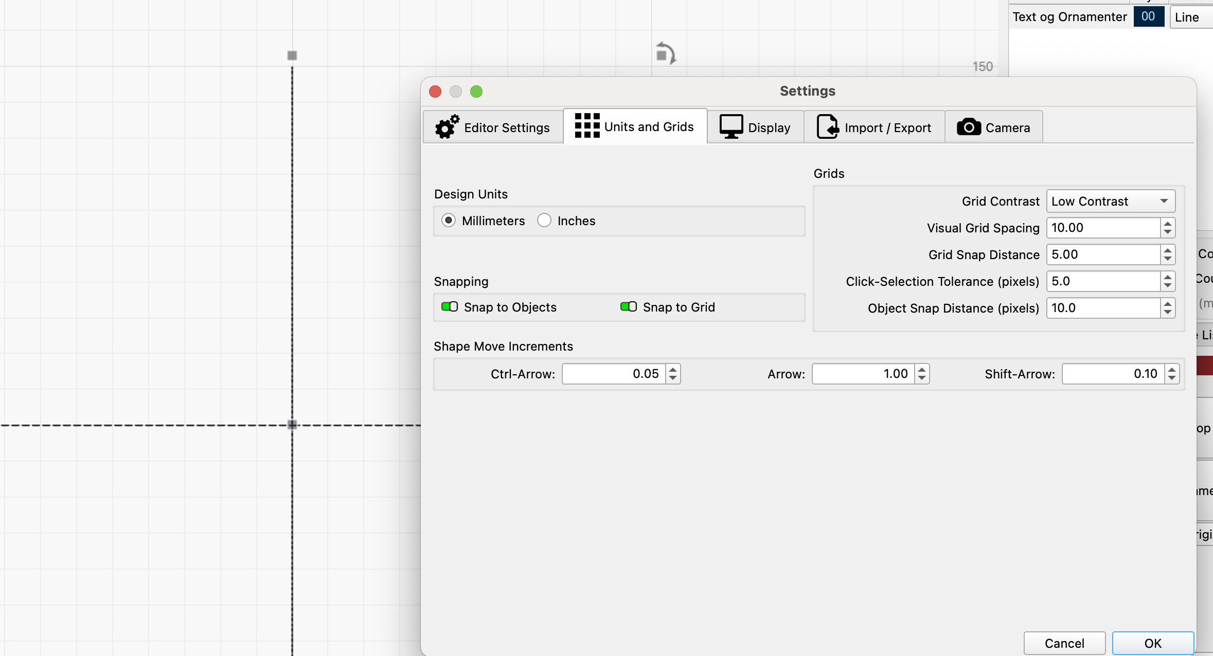
Thanks for the reply. I’m open to the possibility my problem is operator error. It usually is. Here is the file for you to peruse.
compass rose 2.lbrn2 (27.1 KB)
There is an “inaccuracy”, visible in the center, of about 0.01mm. Whether that is the reason for what you observe, I don’t know (yet)
I draw your star here on my machine, we will see if it will be more precise ![]()
The drawing follows …

Yes, that is what I see also. Is there some trick to snap to grid that I don’t know? It seems self explainitory.
Here’s my result. I think I’m just a little more accurate in my construction as you have been, but I haven’t observed that snap function did not work properly.
You may need to zoom in more when drawing/snapping or setting up the tollerance slightly.
compass rose 2-retur.lbrn2 (32.4 KB)
I just tried drawing a box on a new project. I went from the upper left, down, to the right, up and to the left. This is what i got.
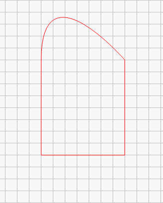
I double left clicked at each change of direction… I don’t understand.
Are you saying that is the nature of the beast and I is good enough?
If you do not want to use the tool designed to draw a rectangle, then hold down the Shift key, single -click on direction changes and double clicks to close/exit.
1 Like
I downloaded the file and found a small error but I couldn’t correct it. When I designed it, it was giving simular errors, until I node edited the diagonals and the cross lines and pushed L to straigthen each of these 4 lines. They now were all exactly intersecting at the same point, even when zoomed to max.
I did a test on your file. Node editing the cross lines and diagonals fixed the problem. The lines were not straight.
That is most likely a result of the method of using the line tool. Vince noted in a recent post that he double clicks on the corners, that will cause the line to be in curve mode, and if the mouse moved ever so slightly in that process it would cause a slight bend in the line.
Vince, you should only single click on any points if you want the lines to be straight.
The docs explain and the video gives a good visual clue to the problem.
Thank you all for your help. I have concluded my problem was user error as I originally suspected. I did re-draw the project and it is perfect. the best tip was to not hold down the left button while drawing the lines. This helped quite a bit.
1 Like
This topic was automatically closed 30 days after the last reply. New replies are no longer allowed.