I did a cut with the test pattern on my Laser, the 9 circles and a square pattern.
Does anybody know what settings, speed and power is applied to the test pattern ? thanks
What ‘test’ pattern?
If it’s in Lightburn, the power/speed should be available…
![]()
Do you mean the small test file that comes with the machine? In my Ruida there is a test file which looks just a little different, it comes from OMT.
Speed and power are integrated into the file itself, which can be run without LightBurn, directly from the machine.
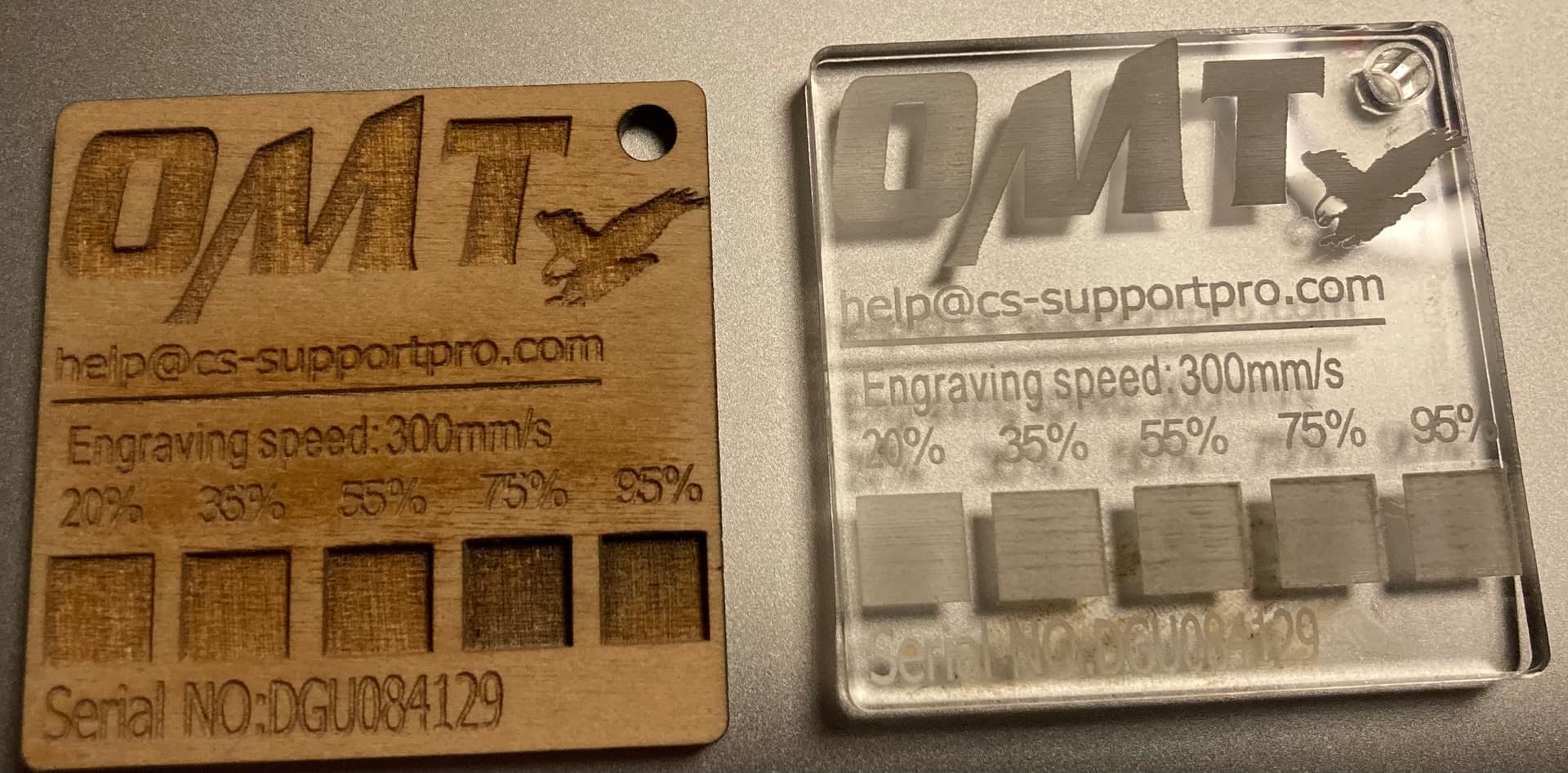
I don’t see that in the supplied OMT ‘test’…
![]()
yes it was integrated in the Ruida controller, i hought second hand but think its a Vevor machine
I’m a bit unsure if you have the file in your controller or not. If you have the file yourself, you can see all relevant values in the display of your controller. If you do not have the file but you would like to have the original test file that matches your machine, you must state exactly which machine you have. Important information is:
The size of the tube in Watts, the bed size and the actual controller type number and year. With this information, you can either be lucky that one of our friends here in the forum has the file for you or that you can get it directly from the manufacturer.
Another option is to download a “neutral” test file or create one yourself in LightBurn, there are 3 different tests in LightBurn.
If you are new to CO2 laser machines, you must be careful to adapt the laser output power to LightBurn and or vice versa, i.e. that you must not exceed the manufacturer’s specified max mA for your tube. The only way to check it is with an ammeter (mA).
Its a Vevor 80 watt machine with a 700mm x 500mm bed. Yes its a file embedded in the controller.
Im cutting 3mm plywood so ive never excedded 30% power which reads approx 10ma on the meter, the tube states 23ma
When you load this file, can’t you see the parameters?
…with 10 mA you are well on the safe side ![]()
Most meters show rms voltage. If yours is one of these you can easily compute the actual current.
if 30% pwm produces 10mA then 100%/30% = 3.333… The power through your tube to produce this would be 3.333 x 10mA or 33.33mA when your tube lases. Exceeding your 23mA limit…
At 50% pwm your meter will read 1/2 of the 33.33mA…
This is no different than reading the pwm output, at 50% it will read 2.5V even though we know it’s being driven by a 5V signal. To get the real reading 100/50 x 2.5V = 2 x 2.5V = 5V.
Make sense?
The tubes current limit should be set by the lps current control.
Good luck
![]()
This topic was automatically closed 30 days after the last reply. New replies are no longer allowed.