Until I hacked the lid switch to its Water Protect input, the power supply had only two digital inputs from the Ruida controller:
IN=PWML=L-ON(low-active)
(Plus ground, as discussed below.)
This scope shot shows how the PWM signal behaves during the test pattern above at 40% PWM:
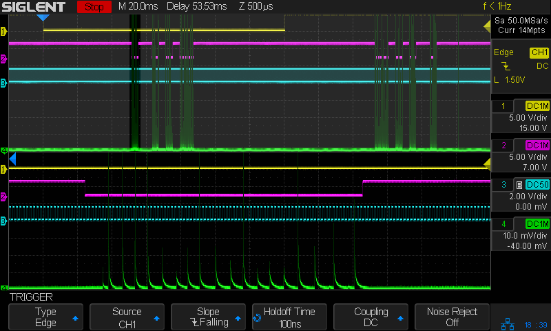
The traces:
- X axis direction = yellow
L-ON= Enable = magentaIN= PWM = cyan- tube current 50 mA/div = green
The upper half of the screen shows two complete scans, left-to-right and right-to-left, through the pattern. The scope triggers on the X axis DIR signal going low at the start of the left-to-right scan, which happened off-screen to the left.
The lower half of the screen zooms in on the left bar of the pattern during the left-to-right scan. The Ruida controller runs the PWM at 20 kHz, with the duty cycle set to 40% throughout the entire scan line. The PWM signal does not change, even when the laser output is off in the blank sections of the pattern and on either side of the entire pattern.
Instead, the L-ON signal controls the laser output, with the laser tube current showing the chaotic pulses I described in some earlier blog posts. The laser is active only when the L-ON signal goes low during the engraved parts of the pattern (apart from those pesky random speckles, none of which happened here).
The scope signals come through coax cables wired to the controller outputs, but they’re identical at the HV power supply inputs at the other end of the wires. In fact, I started measuring them at the power supply, but the controller connectors were much more accessible.
The signals run with a paired ground wire connected to the controller GND at one end and the power supply GND at the other. You and I may well have done it differently, but there’s no sign of ground bounce / noise / interference in the as-wired digital signals at either end.
Unfortunately, it looks like the glitches come from inside the power supply, regardless of the L-ON signal.