Where Those Random Dots in Engravings Come From

I don’t believe that’s the case. “Enable” is the LPS’s safety (like a firearm). If not enabled, you can pull the PWM trigger and it won’t fire. It should hit the enable then PWM tells it to stay full on, full off, or modulate something in between.

But, now that I look at the prob you document, this isn’t what I was thinking- I was thinking that this is glitchy HVLPS that can fire once briefly after Enable becomes true without anything on the PWM. But that’s not there, they’re not just happening at the start.

I don’t know, I haven’t seen this. If so I’d be scoping the inputs to the HVLPS and decide if the HVLPS is actually defective or somehow the Ruida or the way the Ruida is hooked up.

I’d first make sure the HVLPS uses the same low voltage DC ground as the Ruida. This is the behavior I’d expect to see if we connect wires for Enable and PWM-Out to the HVLPS but no ground wire to the Ruida or its 24VDC supply (same thing, they’re tied together, but connection at the Ruida is more correct than connecting at the 24VDC supply).

Until I hacked the lid switch to its Water Protect input, the power supply had only two digital inputs from the Ruida controller:

  • IN = PWM
  • L = L-ON (low-active)

(Plus ground, as discussed below.)

This scope shot shows how the PWM signal behaves during the test pattern above at 40% PWM:

The traces:

  • X axis direction = yellow
  • L-ON = Enable = magenta
  • IN = PWM = cyan
  • tube current 50 mA/div = green

The upper half of the screen shows two complete scans, left-to-right and right-to-left, through the pattern. The scope triggers on the X axis DIR signal going low at the start of the left-to-right scan, which happened off-screen to the left.

The lower half of the screen zooms in on the left bar of the pattern during the left-to-right scan. The Ruida controller runs the PWM at 20 kHz, with the duty cycle set to 40% throughout the entire scan line. The PWM signal does not change, even when the laser output is off in the blank sections of the pattern and on either side of the entire pattern.

Instead, the L-ON signal controls the laser output, with the laser tube current showing the chaotic pulses I described in some earlier blog posts. The laser is active only when the L-ON signal goes low during the engraved parts of the pattern (apart from those pesky random speckles, none of which happened here).

The scope signals come through coax cables wired to the controller outputs, but they’re identical at the HV power supply inputs at the other end of the wires. In fact, I started measuring them at the power supply, but the controller connectors were much more accessible.

The signals run with a paired ground wire connected to the controller GND at one end and the power supply GND at the other. You and I may well have done it differently, but there’s no sign of ground bounce / noise / interference in the as-wired digital signals at either end.

Unfortunately, it looks like the glitches come from inside the power supply, regardless of the L-ON signal.

@ednisley the Ruida controls the LPS differently than the K40 with either stock M2Nano or any of the after-market boards and I wonder if this problem shows up when the LPS is driven the opposite way from the Ruida. ie, LPS-IN = analog voltage from a 1K POT across 5V/GND and LPS-L gets PWM at 5kHz.

In this configuration you’d lower the delivered power by lowering the DC voltage on LPS-IN to get into the less than 30% power range. From my understanding of the industry, Ruida was around before the K40( cheap laser machines and cheap multi-function LPS’s. ie Powers both stepper motors and controller along with laser control) so maybe this is a side effect of they cheap LPS driven with PWM on LPS-IN and output control on LPS-L.

Given the multiplicity of different “K40 power supplies”, I’m pretty sure all generalizations are wrong, including this one. :grin:

Basically, I have no idea what’s going on with any of those K40 supplies, other than that there’s no way to distinguish problems due to the internal design from problems due to off-label external driving circuitry.

For the HV supply in my OMTech, though, the problem is straightforward: the tube will occasionally fire with the Enable input inactive.

Given how many people see exactly the same symptoms, the problem seems regrettably common. If this is due to a “defective” supply, there are a lot of duds out there.

What is listed is not a particular LPS but a variation on how the LPS is driven to gain output. All of the K40 machines I’ve seen in person and online are controlled via the LPS-L signal with a DC voltage input into LPS-IN. Jack put a scope on the laser output and saw that the best way to really limit the maximum laser power output was a POT inside the LPS which really limits the peak output instead of what LPS-IN does which creates a PWM average on the laser control circuit.

I would not be surprised if these LPS’s were initially designed to operate in the K40 default configuration and only later driven the way you’ve seen with the Ruida controller. This is why I was wondering if changing the operating mode changed or eliminated the LPS glitching. So far, IIRC the only machines glitching are Ruida controlled.

While I wasn’t specifically looking for it, feeding a pure analog signal into the power supply does not eliminate the random glitches:
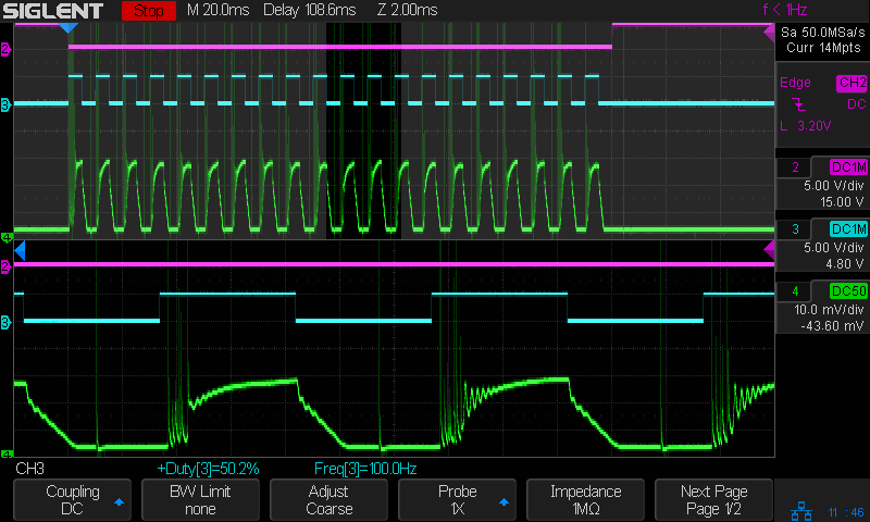
  • L (-Enable) - magenta
  • IN (PWM / analog) - cyan
  • tube current 10 mA/div - green

The spikes in the green trace across the bottom happened when the analog input should produce zero current. The L input is active, but the output current should not glitch in either case.

Background and more details on where that trace came from:

No, which is not surprising, because the power supply filters the PWM down to its equivalent analog value, so putting a trimpot on what should be the analog input isn’t any different than feeding it a PWM signal, with the caveat the PWM carrier must be far above the filter cutoff.

Ah, I wasn’t aware that both the IN(pwm) and L(enable) were reduced to analog inputs. I guess I need to get to Don Kleinschnitz Jr.'s schematics on the makerforums.info site and see if I can recognize that.

But if both inputs are identical I wonder why they label them differently(IN vs L).

I think they’re not: the IN terminal has the PWM filter, the L input is intended for digital control.

Feeding a PWM signal into the L terminal depends on it not being filtered to the analog equivalent.

I was feeding a very low frequency PWM signal, well below the filter cutoff, into the IN terminal, so it looked like a full-scale analog input signal. When it’s low, there should be no current output and the tube should not fire. The glitches show the power supply cannot suppress whatever is going on inside the tube, no matter which input says there should be no output.

Yet the LPS, if its design even loosely resembles the design for the cheap K40 would never see the IN input go to zero because it was tied to the power control POT and you just don’t turn off all output by turning the POT to 0V. Now some people did run it at full 5V but they also quickly wore out their laser tube and many just got rid of the machine at that point.

Putting a 5kHz PWM on the L input is what K40 controllers do which is quite different from running the L input low for long periods of time during a burn. K40 controllers will run the L input with 5kHz PWM with short sections of being low. It’s this operating mode which has me wondering if the circuitry is more apt to glitch when L is held low for long periods while IN is pulsed vs L being pulsed and only short periods of being low and IN being held constant during the engraving/cutting operation.

Original design had you set a power level on the POT, run the engraving/cutting layer, adjust the POT to the next layer’s power level and run that layer of engraving/cutting, etc. VERY different from how it’s done via Ruida control using L for enable/disable and lots of variations of PWM on the IN input.

Also on the makerforums.info was a post to a LPS schematic:
Paul_de_Groot

Oct '16

Power supply schematic
https://drive.google.com/file/d/0BxRBPjkKUvRUN1Q3OTlqNFhVQkJnYW5VTjRXUWduaEp5Wnd3/view?usp=drivesdk

I also looked at the users manual for standard LPS and it looks like in all 3 cases the IN signal is used for power/energy setting and the L signal is used for PWM which is unlike how Ruida says to wire them.

Which is the unanswerable question. It is surely similar, if only because there are only so many ways to build a cheap flyback HV current-source supply, but it is certainly different.

After seven years, it seems the Google Doc link to that schematic is dead:

You need access. Request access, or switch to an account with access.

Which is why I think it’s only useful to measure what actually happens in the laser in hand, used as it’s intended to be used. Speculating about the effects or relevance of tweaks for different power supplies without reliable documentation for any of them seems unproductive.

At this point, I have evidence the generic power supplies for OMTech-class CO₂ lasers will occasionally fire when the Enable (‘L’) input is high or the analog (IN) input is low, either of which should prevent any output, in what is basically normal operation.

Admittedly, that’s evidence from a sample of one.

On the other paw, I have three power supplies sporting three different brands, all of which have visually identical ZYE boards inside. Other folks with similar lasers report similar problems, so I doubt I have the only dud in the world.

On the gripping hand, if anybody wants to fund a deeper investigation, maybe we can work something out. :grin:

I seem to be failing at pointing out that how your machine is wired is NOT how the LPS was intended to be wired since K40 machines are not wired that way. These LPS’s originated for the K40.

Looking at the pdf from this LPS manufacture it looks like all 3 methods of wiring it show the IN signal for energy/power setting and the L signal for pulse control… you have to check the box and then click download to get the pdf. Also notice that the labels are not centered over the pin diagram but they are consistent so easy to recognize where IN and L inputs are.
http://en.jnmydy.com/companyfile/2.html

downloaded pdf and attached. just change the extension.
K40-psu-schematic.pdf.lbrn (30.8 KB)

Perhaps I am being thick as the proverbial brick, which would certainly not be the first time.

The power supply has an internal twiddlepot to set its maximum current, a power control IN (analog or PWM) scaling the output current down from that value, and an Enable input (H or L, depending on polarity) to turn it on. Conveniently, the controller has two outputs: one (choose analog or PWM) to control the power and the other to turn it on and off.

It works exactly as those controls would suggest.

How else could the controller and the power supply be wired together and what advantage would accrue from doing so?

If there is an advantage to be gained by wiring them differently, why would all non-K40 lasers with Ruida controllers arrive miswired from the factory for all these years?

It’s a much nicer version of the K40 schematic than most of the others. Thanks kindly!

I can’t believe that internal POT is there for user configuration and it is NOT the POT mentioned or shown in the User Manual shown below. Instead they say the controller DAC(Digital to Analog Converter) should be connected to the IN input.

The L-ON output from the Ruida is being connected to the IN input of the LPS when really it should be L-ANI(analog). and the LPWM should probably be connected to the LPS L input.

It has worked but it is not per the manufacturers recommended configuration. Hence why I keep bringing it up.

Maybe it will work better wired as the manufacturer suggests and the DAC output of the Ruida controller goes to the IN input and the L-ON goes to the L input. I think all K40’s with stock and after market controller boards use only one control input to the LPS via the L input and either the IN input is pulled to 5V or it is set with a 5K POT as shown in the diagram from the manufacturers User Manual above. ie putting an analog voltage into the IN input.

I have no idea why Ruida did this when they jumped onto the K40 bandwagon. The K40 and these cheap Chinese Laser Power Supplies were not shipped with Ruida controllers. Those controllers cost as much as the entire K40 laser machines. Instead, the K40s shipped with a M2Nano controller and was wired how I mentioned above, ie controlling only LPS-L and LPS-IN was set via analog voltage via a POT.

That would be the LPS schematic, not a K40 schematic but there are hundreds of K40 schematics out there. But if you want more information on how K40s are wired and about the internals of these cheap laser power supplies, yes it’s very different from what Ruida says, here’s a good site.

Turns out it works worse, because the analog output does not come from a DAC, but is just the PWM output sent through a low-pass demodulating filter inside the controller (*). Because the power supply also has a demodulating filter (which is why it uses the same pin for both analog and PWM input), putting two filters in series reduces the signal bandwidth:

Background of that plot:

So they’re pretty much equivalent and the analog signal does not eliminate the glitchiness.

Here’s the PWM version:

  • L-ON - magenta
  • PWM - cyan
  • current 10 mA/div - green

Switching to the analog output shows the reduced bandwidth in the rounded transitions:

  • L-ON - magenta
  • analog - cyan
  • current 10 mA/div - green

The glitches in the upstream post came from a 100 Hz PWM carrier frequency at 50%, which the HV supply treats as an analog signal because it is two-ish octaves below the filter cutoff.

Because the power supply sends both the analog and PWM signals through a low-pass filter, they produce a control voltage at the same circuit node inside the supply and control the tube current the same way.

TL;DR: I’ve measured the results both ways and the power supply produces the same results: there is no difference in tube current control between PWM and analog signals. The additional filter does rolls off the analog signal at a lower frequency, so PWM is better when you care about fine details or high resolution.

(*) For a KT332N, but DACs are expensive and RC filters are cheap. Even if the first Ruida controllers had DACs, I’d expect RC filters to appear during the first round of cheapnification.

1 Like

We’ll just have to wait and see if anyone sees this glitching effect who doesn’t use the Ruida method of control. All other controllers don’t vary the LPS-IN signal but to use it for setting the max LPS output current and all on/off and power control is done by 5Khz PWM on LPS-L. Having seen scope traces of the LPS output, it does make more sense to set the max current output using the LPS internal control POT but asking consumers to stick stuff into the HV power supply is asking for legal issues.

It looks to me like the Ruida is setup to drive these cheap Chinese LPS units in dual control mode. I don’t know if this has anything to do with these LPS’s glitching but it’s definitely a different way of control from their original design. These cheap Chinese LPS units didn’t show up in til around 2015 in the K40 machines which were in the $350 price range. Ruida was originally designed to control Full Spectrum Pro-Series CO2 machines back in 2012 and then the Trotec Speedy in 2013. I’ve yet to find anything on those LPS units except that they are over 2x the cost with a 90W being $600, 120W being $800 and 150W at $1000. The machines today, even a low end 45W, are over $4,500 so I would hope the LPS is of a much better design.

Either way, it sure looks like when both inputs are active and one of them(L or IN) are low the LPS doesn’t like it and still pulses the output and that shouldn’t happen.

My assumption (and I know what that word means :grin:) has been that a commercial laser will arrive from the seller with its power supply twiddlpot preset to the maximum current for the laser tube in that machine. Similarly, a “60 W” replacement supply will arrive preset for more-or-less the correct current for a “60 W” tube from that seller. In either case, there’s no consumer interaction required or expected.

Which seems true for the three HV supplies I have. They all produce about the same 25-ish mA max current, but each has a different twiddlpot setting: the factory techs definitely adjust the pot to produce a specific current. We all know 25-ish mA is how OMTech (and others) wring an alleged 60 W out of a 1 m tube: having a twiddlepot doesn’t preclude overdriving the tube!

Conversely, anyone inclined to tinker inside / “improve” a laser or build one from scratch must do a whole bunch of system-level integration / configuration / testing far beyond the consumer level, so it doesn’t seem unreasonable to expect those folks to perform what’s ordinarily a factory adjustment. Setting the current does not require opening the power supply, doesn’t expose you to high voltages, and uses only common tools. Admittedly, it might require adding a DC milliammeter to the HV circuit, but the OEM supply in my laser included a digital meter and tinkers generally add a meter as one of their first mods.

So it seems reasonable to think the twiddlepot is intended to (and actually does) set the maximum recommended / allowed / peak tube current, with the PWM / analog value scaling the operating current between 0% and 100% of that current. The usual caveat about improving the tube’s lifetime by rarely exceeding 70% of its maximum current translates into a sensible, consumer-friendly meaning of rarely exceeding a 70% “power” level. OEMs setting the twiddlepot to an “optimistic” current just take advantage of the situation.

Choosing a different twiddlepot setting can certainly make the supply harder to use, but what’s the point in that?

Aye!

One would hope that’s the difference between the top-dollar supplies found in high-end commercial machines and the bottom-dollar cost-reduced supplies we have. It would be interesting to measure what goes on in those machines, but my toy budget won’t stretch that far.

Ok, so I have done a bunch of testing with my cheap chinese laser and I found that when I pull out my focus 2-3mm, the dots go away. I created a series of .1 and .3mm wide vertical lines 12 wide 1mm apart. While the laser was running, I slowly defocused until the dots went away. I found that I was about 2-3mm away from my sharpest focus but the dots did disappear. Someone else try this and let me know if it works for you!

No surprise: spreading the same beam energy over a larger area reduces the energy density below the level required to damage the acrylic. The random tube firings still happen, but they no longer produce visible zits.

However, a defocused beam also reduces the beam’s ability to create the damage you want in the filled areas, by requiring either more power or slower speeds, in addition to blurring the edges & fine details.

Defocusing is a useful tradeoff, but it is a tradeoff.