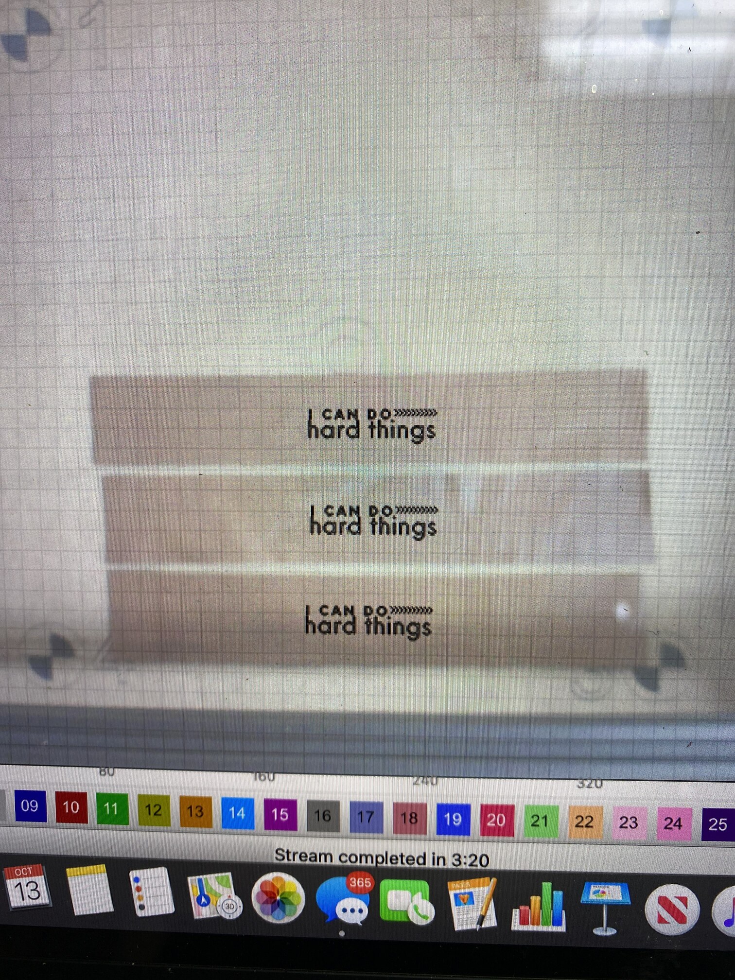
@LightBurn, Do you have any idea why my images aren’t engraving where they show in preview? This is the second burn that I did where this happened. It seems the closer I go to the center of my bed, the graphics seem to end up lower on the piece I’m trying to engrave.

I am curious as well… I am trying to find out somewhat the same problem.
Although it seems in my case it appears the further away from the center the more off the camera is.
Didn’t have time to dive fully into it.
What kind of camera do you have?
I have the lightburn camera, 160 degree. I just got it this weekend, and after a nightmare experience with a different camera I bought, I’m just glad this one works! But it would be far better if everything lined up perfectly  I’m hoping it’s an easy fix.
Are the items you’re engraving on closer to the camera than the target marks were when you first did the alignment? The camera system in LightBurn assumes a couple things:
- The camera is at a fixed position and angle relative to the X/Y gantry of the laser
- The camera is at a fixed distance from the top of the material
The second point there means that if you have a laser without a movable bed height, and you focus the lens differently for materials of different thickness, you’ll have a harder time using the camera. Not impossible, just not as easy. If you are using a backstop of 3/4" wood that you weren’t using before, you’ve changed the distance from the material to the camera, and you’d need to do the alignment for that distance.
You can actually do multiple alignments and save them by right-clicking in the camera control window and clicking ‘Export’. If you calibrate for 1/8", 1/4", 1/2" etc and save them with names like that, just load the appropriate one when you use a different material thickness and that will work. It’s not ideal, but there’s no simple way around it for now.
2 Likes
Thank yiu so much for responding @LightBurn. My camera is at a fixed height and angle, I have the Roddy Roman camera mount on an Ortur Laser master 2. ALso, the materials I’m engraving are almost flat, so consistent with the target marks I engraved for the alignment. Is there anything else I could be missing?
Is the camera at all loose in the mount? If there’s any play at all it can mess things up.
So if the camera alignment is that sensitive that the slightest shift from the alignment position will throw it out. How do you then compensate for the lid of the machine not being exactly in the same position every time?
Do you run alignment each single time you want to use the camera?
I just installed my camera today and experienced exactly the same issue. My engraving was way off … and yes the lid was in a different position to when I ran the alignment.
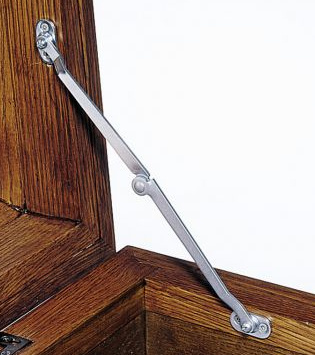
Seems the only permanent solution would be to setup a jig to hold the camera without mounting it to the lid…
Something like this on the lid to ensure it opens to the same place (or a small steel cable with eyelet ends):
Hey Oz,
Yes I agree that would work.
Though about this problem all night, and I think I might move away from the whole mounting on lid idea. I might build a frame (foldable) to straddle the width of my bed (1000mm) with locator pins on the machine for repeatability and an exact height every time.
My camera isn’t loose, and it’s fixed. So for the time being, I’ll just make sure to engrave towards the bottom of my laser bed, which is where I have good results.
@Nova_Star I’m glad I’m not the only one who does my best (and most inconvenient!) thinking at 3 am😅
Angie
That’s best time time to think ! 
OK, today I ran into the issue of needing multiple alignments for different thicknesses.
Can you walk me through that even more step by step? Meaning, will I need a large board at each thickness to engrave my targets onto?
My laser bed (lasermaster 2 20 watt) is almost 20x20 inches. So will I need a 1/2 inch board of that thickness that fits my bed to make a 1/2 inch size test grid? then another that is 3/4 by 20x20? Or can I make a much smaller test grid yet still have my camera calibrate for the whole size of the bed with a small test piece?
I hope I’m explaining this ok,lol!
@oz
The board itself just needs to be large, not thick - If you have a few 1/2" pieces of scrap and lay a piece of cardboard over them, that would be enough to do the calibration.
In the Camera Control window, right-click, choose ‘Export’ and save the the settings you’re currently using as something like “CameraSettings - 0 inch”. Then place your scraps on the bed, and the cardboard on scraps, and do the new alignment run. When finished, right-click again and export that as “CameraSettings - 0.5 inch”.
… and so on.
When you want to use the camera settings for different stuff, right-click the camera window and import the appropriate camera alignment file for the material thickness you’re using.
Not quite step-by-step, but did that make sense?
1 Like
Yes, this is very helpful!!! I will be making some settings in the next few days. I appreciate your help!
that is probably fix to my issue too
This topic was automatically closed 30 days after the last reply. New replies are no longer allowed.