Wobbly or bad shaped figures using Sculpfun S30 Pro Max

Hi everyone,

I just unboxed my S30 Pro Max and I’m having trouble with both linear shapes and fill operations.

The fills look terrible — they start from bottom to top, and around 60–70% of the way through, they shift or misalign.
When drawing lines, especially circles, the shapes come out like eggs or ellipses, and sometimes they’re not even closed.

What frustrates me the most is: why does the fill start correctly and then go off track?

How can I properly set up my machine to achieve clean cuts and engravings as expected?

Thanks in advance for your help!

Things that I’ve done so far:
I’ve tightened the Y belts (not sure how tighten they should be)
I’ve tightened the X belt (same question as Y)
I have the Y capacitor turned to 90 degrees right. X motor points at 0 degrees.

Here some pics of testing


![WhatsApp Image 2025-07-28 at 18.49.16_e548e5f8|375x500]

(upload://1lyYq1cflhxwinXT8LYKeH08vTs.jpeg)

Looks like mechanical issue. I would check all set screws for loosness on all drive pullies and couplers.

This may help…

1 Like

That’s wrong. Do you have the extension kit? Then you should turn it 45 degrees. If you don’t have that kit, do not touch the reference voltage!

Check the guide posted above and go through all the steps mentioned there.

2 Likes

Hi

Yes I’m using the extension kit. Forgot to mention it. I’m that case is the set up correct?

Thanks!

No, you still need to turn it 45 degrees backward.

Additionally, with a new laser, it’s best to start with the standard frame, before extending it. The extension kit adds quite some mechanical challenges to the setup.

Thanks for the reply. Unfortunately for the need of the project I need a wider area :disappointed_face:.

Still, when you say turn 45 degrees means diagonal right? In the photo I have just Y motor at 90. Am I correct?

Yes, diagonal. Here is a guide: Workspace extension kit - Diode Laser Wiki

Even if the project is bigger, it’s good to get experiences with the small one and rule out all issues and then upgrade :grinning_face: But you will get there as well. Just might take some tries longer :grinning_face:

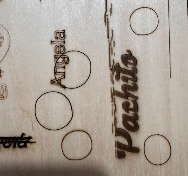
The out-of round circles are showing a little bit of backlash or looseness. The easiest way to find this is to slowy wiggle the laser module with the power off to see where the available motion comes from. You wouldn’t need to push hard enough to turn any of the stepper motors.

Pushing the laser module quickly can cause one of the stepper motors to rotate quickly. This can generate a voltage spike and destroy the stepper motor driver chip on the controller.

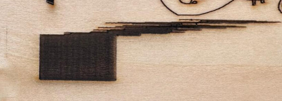
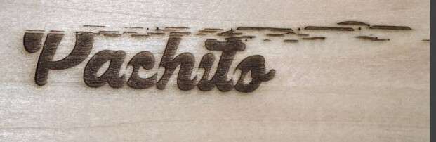
The progressively scattered nametag engraving looks like it’s related to Overscan.
Overscan is a feature where the laser module overshoots the end of an image while engraving.

This allows the speed across the engraving to be held constant and allows the engraver some room on each side of the artwork to slow down, stop, reverse direction and speed up to the commanded speed of the engraver.

When the speeds are high, the overscan is larger. It takes more room to slow down. The art must be moved further away from the edge of the work area to make more room. The progressive scattering happens in one direction (at the end of the nametag). It’s showing that you’re engraving an image or ‘filling closed shapes’. This is all set correctly and looks good!

I believe that the laser module is hitting the frame or chassis on the side closest to the beginning of the nametag. The progressive scattering away from the beginning will stop when the nametag is far enough away from the frame or chassis to allow the engraver to apply the overscan.

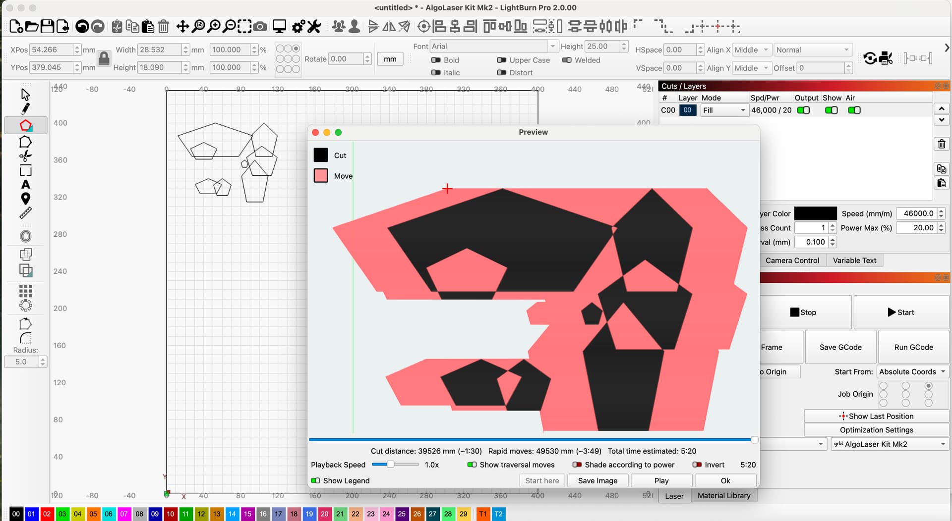
The expected overscan behavior can be inspected in the Preview window. With your project loaded in LightBurn, click Window in the top row, and then Preview. It’s near the top.

In this window you’ll see the project as the laser would receive and understand it. You can zoom in and out with the mouse-wheel. If you’re seeing red travel lines, you can see if the overscan is crossing the workspace. If the red lines aren’t there, you can enable this visualization tool by enabling the switch marked, “Show Traversal moves”

Here, the quick sketch is showing the overscan (on filled overlapping closed shapes) extending beyond the workspace (the green line).

The art needs to be moved to the right in the workspace in LightBurn, so the overscan can’t drive the engraver into the frame of the engraver.

In this example I set the speed excessively high to exaggerate the overscan behavior.

When you need to make a large project that is close to the limits of the engraver, you can cut both speed and power to reduce the overscan to maximize the size of the art that you can produce with your machine.

2 Likes

I’ve turned on the machine today and throws

ALARM:9

Homing fail. Could not find limit switch within search distance. Defined as 1.5 * max_travel on search and 5 * pulloff on locate phases.

Is not moving on Y axis and I reseted everythin with RST=*. I’ve removed the GBRL machine and then linked it again… Nothing changed

Only thing that I did was move 45 degrees the screw and try to fix it putting back again at 90. Nothing changed, same error.

Do you know what happened?? Why these machines are so… omg..

This is likely the reason that homing has failed.

Mark the motor shafts with a permanent ink felt pen; Jiffy or Sharpie are common brands.
Mark the pulleys (or sprockets) that drive the machine. This helps make it easier to see which parts turn and where the turning stops.

Occasionally the set screws or grub screws in the pulleys will work loose. Please test each of the set screws with the L-shaped Allen Wrench or hex key to confirm that they are tight. They can look tight without being tight.

While it moves along the Y-Axis, the gantry can drift ‘out of square’ and begin to bind. This can cause partial loss of motion or full loss of motion. Please confirm that the gantry moves by hand by moving it slowly. Unpowered, the gantry must move freely and turn the motors. It is critical to move slowly as rapid motion of the mechanism can cause damage to the controller. Again, the felt pen markings on the motors and shafts help improve visibility and assist in confirming motion.

If the gantry of the laser engraver was moved suddenly, fell, or was dropped, resulting in the gantry moving quickly, the controller may have been damaged. If the gantry is free moving, if the set screws are tight and if the pulleys and shafts move as expected, the next tests will confirm if the controller is intact or if a broken wire is causing problems.

Please confirm at your convenience. I’m hoping that something has worked loose from possible overscan collisions.

Thanks John… before doing all of that I noticed weird paramters in GBRL. or that’s what ChatGPT says

$$
$0=10
$1=25
$2=0
$3=4
$4=0
$5=1
$6=0
$10=1
$11=0.010
$12=0.002
$13=0
$20=0
$21=0
$22=1
**$23=0**
$24=200.000
$25=3000.000
$26=250.000
$27=5.000
$30=1000.000
$31=0.000
$32=1
$100=80.000
$101=80.000
$102=250.000
$103=100.000
$104=100.000
$105=100.000
$110=6000.000
$111=6000.000
$112=1000.000
$113=1000.000
$114=1000.000
$115=1000.000
$120=1000.000
$121=1000.000
$122=1000.000
$123=200.000
$124=200.000
$125=200.000
**$130=935.000**
**$131=925.000**
$132=200.000
$133=300.000.

$23=0 says is for homing from down left. But it keeps going just X right. When I execute $RST=* these values changes:

$$
$0=10
$1=25
$2=0
$3=4
$4=0
$5=1
$6=0
$10=1
$11=0.010
$12=0.002
$13=0
$20=0
$21=0
$22=0
**$23=7**
$24=200.000
$25=3000.000
$26=250.000
$27=2.000
$30=1000.000
$31=0.000
$32=1
$100=80.000
$101=80.000
$102=250.000
$103=100.000
$104=100.000
$105=100.000
$110=6000.000
$111=6000.000
$112=1000.000
$113=1000.000
$114=1000.000
$115=1000.000
$120=1000.000
$121=1000.000
$122=1000.000
$123=200.000
$124=200.000
$125=200.000
**$130=400.000**
**$131=410.000**
$132=200.000
$133=300.000
$134=300.000
$135=300.000

Why is this happening? On sunday I just turned off a machine that was doing weird circles and now is not able to home and I didn’t do anything! Just moved the screw 45 degrees and turned it back to 90. Nothing else.

Here what the maching is doing:

Now… I dismounted the Y motor and tested it by connecting it to a diferent ports. On X port (Red one) works well. On Y sockets (Blue and White ones) tries to move but doesn’t. However, if you hold it, you feel its moves, but the rotor is not moving.

From nowhere the Y sockets got burnt. Are they damaged? Is there any software test I can perform to know what happened?

That sounds like the driver is defective. It can be caused by the 90 degree setting on the potentiometer. Send a video showing the case to Sculpfun and they will send a new mainboard.

The moving directions can be changed in machine settings and might have to be adjusted after mounting the kit.

Hi! Coming back after meassuring Y axis screw

Here the results. This is the voltage regardless 0, 45 or 90 degrees in the screw. Can we conclude its broken?

Yes. The voltage should be below 1.5V at any time, I think.

Generally, the factory settings are correct and safe. Choices will be made in the controller board layout and in the wiring to have the stepper motors move in the expected direction by default. Inverting axes shouldn’t be necessary but it can be an issue.

In the video, the X-Axis motor moves the laser module along the X-Axis until it collides with the frame of the engraver on our right hand side. Stepper motors don’t offer feedback to most controllers. If the control board doesn’t recognize that a limit or end-stop switch is triggered the engraver will rattle away until it gives up searching for the switch. If there is a switch at the limit on our right hand side, it either wasn’t activated or a wiring problem prevented the controller from detecting it.

The $23 setting is set up to invert (reverse) any of the homing directions.
$23=0 : No Axes inverted
$23=1 : X-Axis inverted
$23=2 : Y-Axis inverted
$23=4 : Z-Axis inverted

If you need to invert two axes (or all three) for homing, add the numbers and set the $23 to that value.

To invert the X-Axis and Y-Axis:
$23=3
To invert all three Axes:
$23=7

You can read more about the grbl settings here:

It really depends on how it’s being measured.

The adjusting screw is a variable resistor or potentiometer (same thing - different names). This component can be wired up ‘inline’ to limit current flow or wired across power to provide a voltage (signal) that is in between the power voltage and ground. I don’t have a Sculpfun here but the electronics in the engravers usually runs on 5V and ground should be Zero Volts. The Motors are usually run on +12V or +24V.

If that variable resistor is connected between power and ground and if you’re reading the power pin and the ground pin with your volt meter, it will read identically regardless of the setting. Have a look for a ‘middle pin’ and measure from that to the ground and see if the adjustment works.

I was going to type ‘third pin’ but that could be misleading with a three pin component.

Possibly, but unless it’s very obviously broken, It can’t be known without testing under load.

Burnt parts are caused by overload conditions or under-spec components.

A stalled or Locked-up motor can draw as much as 4 times the current as it would draw when it runs freely. If the Y-Axis is jammed up or binding it could quietly overload the wiring.

That’s true for old-school DC motors, but not for contemporary microstepping motors. The trimpot under discussion sets a reference voltage level for the stepper driver to control the current delivered to the motor windings, so the current remains constant regardless of the motor speed / load / condition.

One thing that can kill the driver stone cold dead: unplugging the motor with the power on. The energy stored in the magnetic field must go somewhere, so the winding voltage will rise until it forms an arc across the connector pins. Depending on a bunch of events that don’t line up every time, this can also raise the voltage on the driver side enough to destroy the MOSFETs (a.k.a. “releasing the Magic Smoke”).

However, that arc will not, in general, have enough energy to char the connector housing. That requires high winding current and a faulty wire-to-pin or pin-to-pin point with enough resistance to generate enough heat to destroy the housing over time.

It makes sense. I think you’re right about this. It shouldn’t draw more current than it’s limited to.. because it’s current limited. (I love circular arguments because they’re so circular.)

This is a great explanation. It reminds me of older cars with ignition ‘points’ and distributors.

I have further follow-on, and I don’t want to divert from the OP’s concerns or (hopefully) emerging solution. I’ll DM you with further questions because I’m genuinely curious.