As you can see in the attached picture the crosshairs activated by LB, “Show Last Position”, depicts the position of my Shapeoko XXL Router. I would like for that cross-hair to reflect the position of the Jtech laser.
How does one set the offset distance of the jtech from the spindle to the laser via macro and/or Light Burn?
Can you please share an example macro for setting XYZ for jogging to a corner jig position for repeatable jobs?
(Let me know if I can provide any more information)
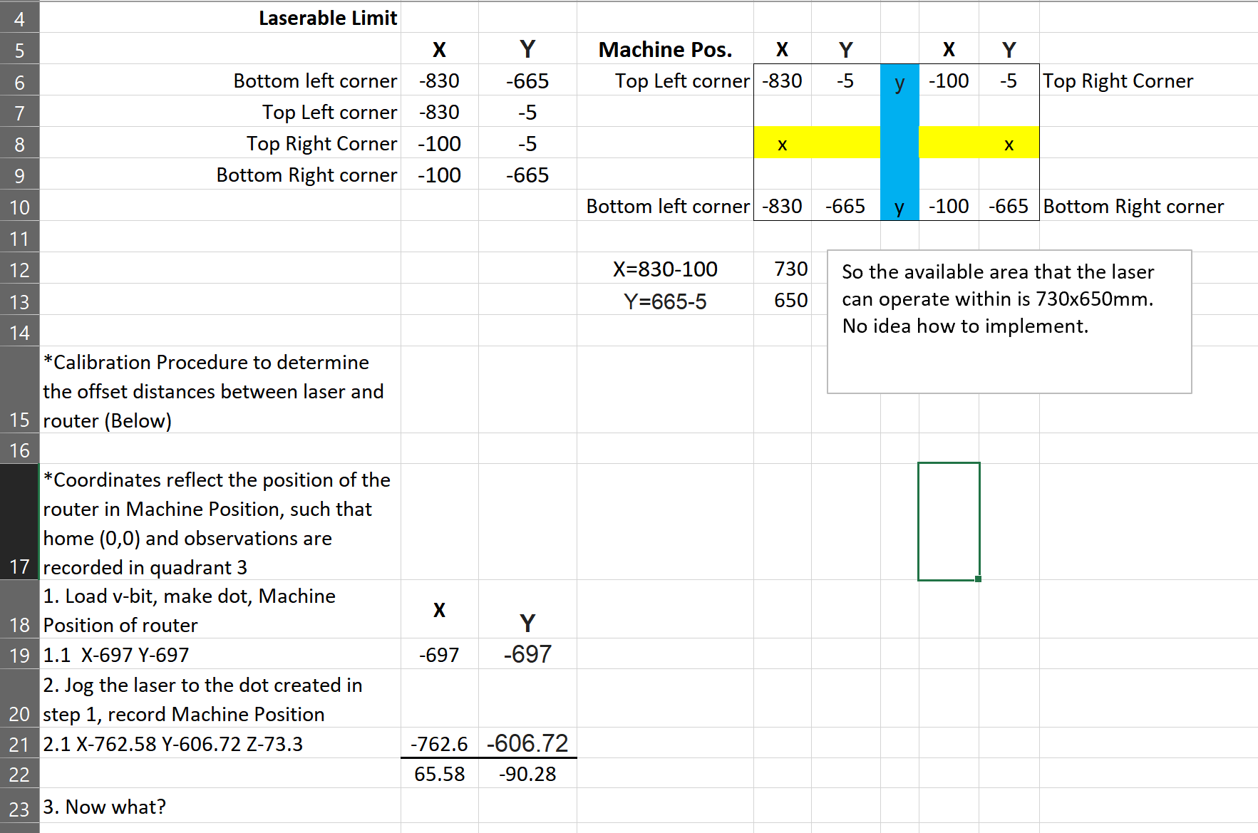
Edit: Add below screenshot of a spreadsheet. The photo shows the distance that I need to offset in Machine Coordinates NOT the inversed coordinate system.
Edit 2: Repaired data in picture shown below
If your machine has homing set up, there’s no need for this - you just create the file using Absolute Coords and the job will always go to exactly the same place on the laser.
If you want the position of the laser displayed, not the position of the router, change the workspace offset you have programmed in to account for the difference, and that should do it, and you’d reduce the working area for the laser by that offset amount.
Ah Ha! Thank you for the Absolute Coordinate advice!
What helped me a lot was experimenting with the various settings and sending G0 X+/-10 Y+/-10 commands and adjusting settings until everything started to make sense. Easy
I have been learning G-code a little bit at a time over the last year, and most of the time, once I get the keywords together, everything starts to make sense.
If it’s easy for anyone to post an example of the Gcode or necessary settings to compensate the Jtech laser Workspace Offset from the spindle. I can verify the recommendation as you may not have the same setup.
I could ask on the Carbide 3D forum as well and report back as I know that it may be a bit off the scope, but I am sure the Shapeoko crowd would dig this type of stepwise clarification.
I will try and figure it out as well, but the hobby CNC newbs like me would substantially appreciate some sort of procedural approach to this.
(Might even just do the stepwise write-up and post on both forums if anyone has types that might help me expedite this)
The current workspace position of the laser is the offset you need
When using the laser with LightBurn, you’ll already have a macro that’s applying a workspace offset. You’d just need to remove the above offset from it (or add, depending on the sign of the offset).
I used Light Burn to fine-tune this offset in conjunction with the readily available Macro for CNC’s “Laser Mode”
After the point is obtained and the delta is calculated I added the difference to the above mentioned macro line G10 L2 P1 X-800 Y-600 (Then tested for accuracy)
Make sure the Show Last Position is on and hit the Get Position button every time. This should update the red crosshairs on the screen. Test, evaluate, adjust and repeat as necessary.
(I am pretty sure this did the trick for me, but I will update accordingly)