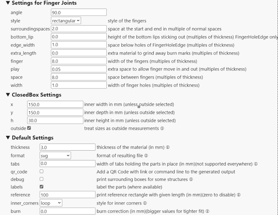
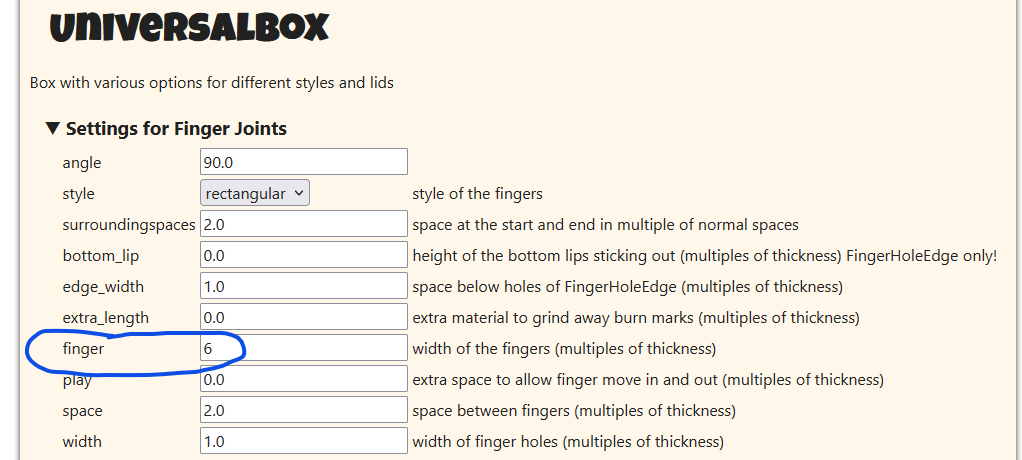
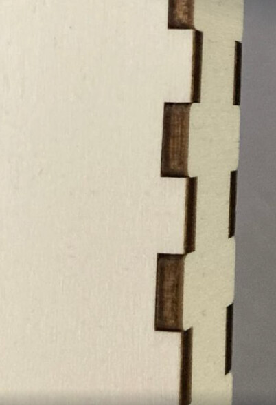
I have a little problem with the boxes. I need to make a good box to have perfect fingers that fit together. But I can’t get it right. Attached is a picture of the boxes.py setup and also the product where you can see the gaps between the fingers. I am also attaching the generated *.svg file. I don’t know what to do anymore, I paid out a lot of material but the result is still the same. There is a gap. Would anyone know what to do about it?
It could indicate that you have kerf setting enabled with a false value.
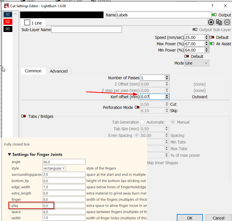
When I use boxes.py, I disable the kerf setting there and use the kerf settings in LightBurn. 0.07 fits my CO2 laser just fine for a tight fit.
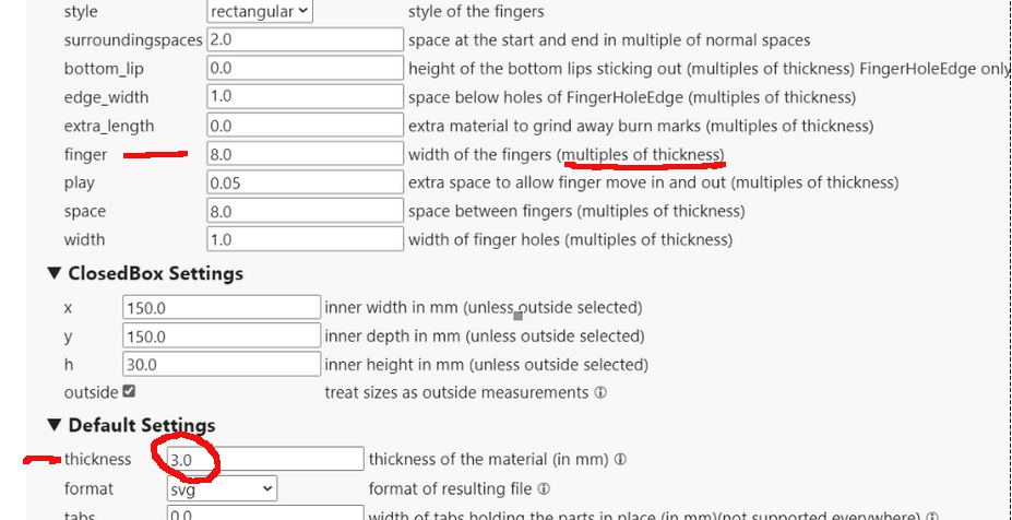
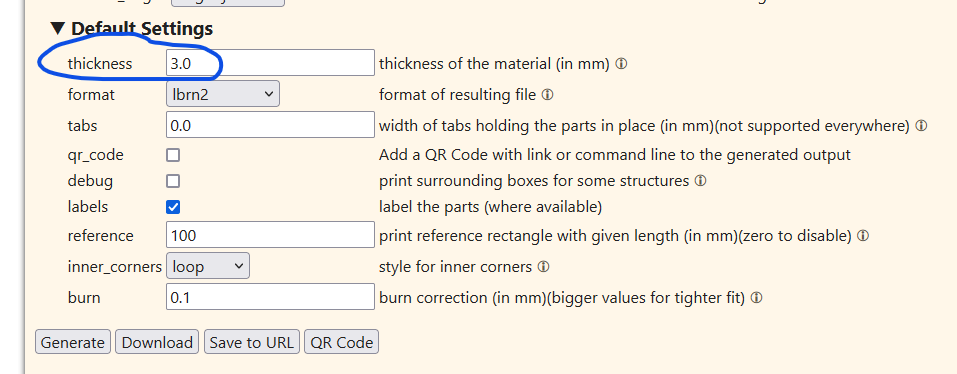
for the rest, have you checked that your material is 3.0mm? Plywood likes to “cheat” with the measurements.
This could make you off 1mm or 2mm depending on the software interpretation.
I’d generate it again and use values that are within the specifications of the software… I only looked at this one… double check the rest of the entries.
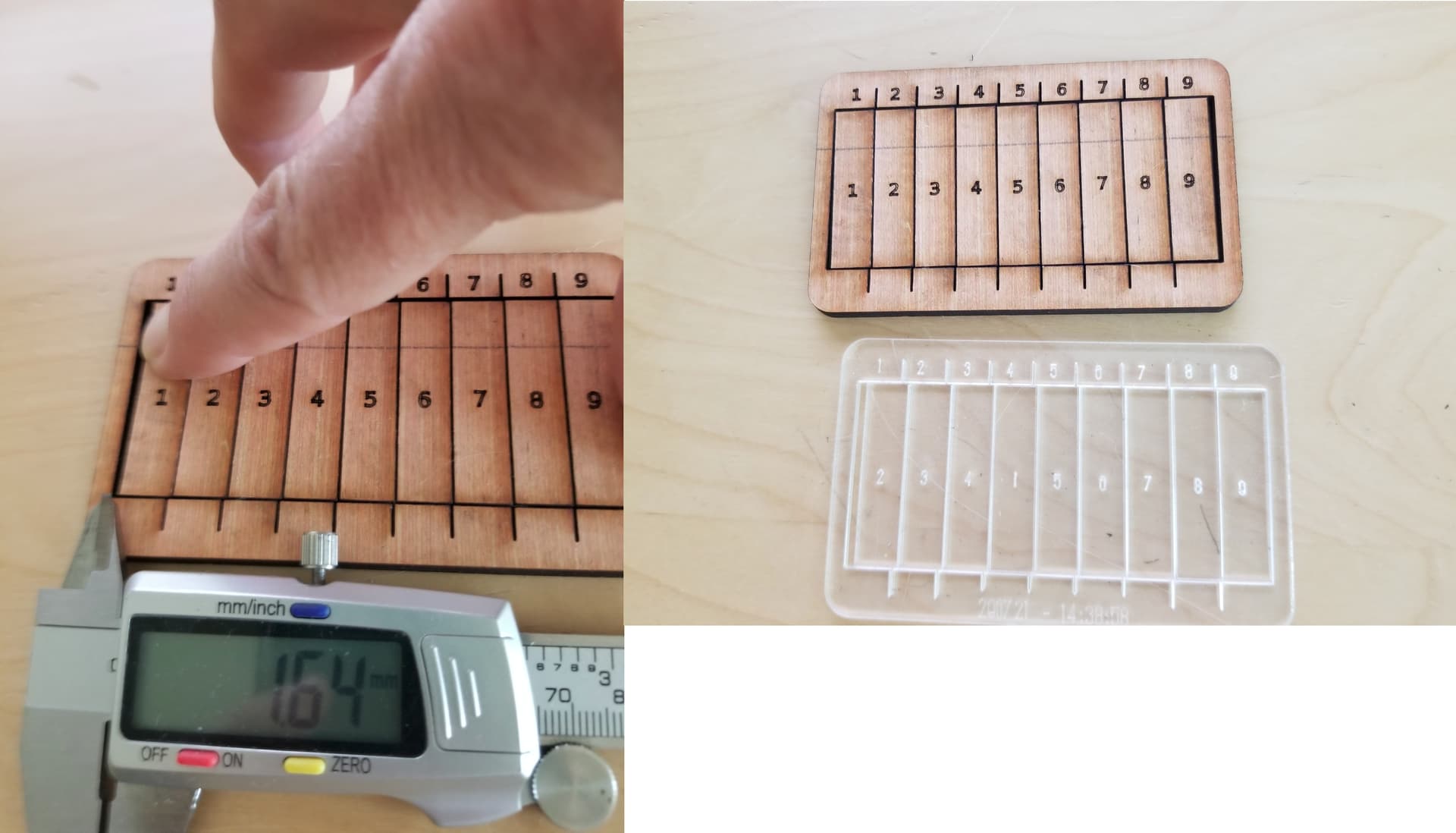
The measured gap is the kerf X 10… so divide the results by 10… In this photo my kerf it 0.164mm with this material… You need to measure it for each type of material.
When you use kerf on a 3d object, you need to split the difference between both parts… In my case I’d use kerf/2 or 0.164mm/2 = 0.082mm for the kerf on each piece.
In addition to the above (all of which I heartily agree with), it looks like you have a value of 0.05 entered for the ‘play’ field, which adds a gap like you describe. I would also make that value 0.
When you are making fitted parts with a new workflow or material, it’s a good idea to make some test cuts of just the bits that need to mate (in this case a tab and a slot), this can save you a lot of material as you work to find the best settings. The modifier tools should help you isolate a test area, if you want to try this! I think boxes.py also has some test tools of their own that are designed for working out the perfect settings to enter into their generators.
I would guess that the software has to deal with the relationship of the thickness being 3mm and the required value of the tab width being a multiple of 3. Not 8mm as a value. It should be 3, 6 or 9 for example. If the software resolves it to 6mm then it will be 2mm off the 8mm tab setting… if it resolves to 9, it will be 1mm off the tab size…
The truth is I don’t know what it does. It could do any number of things…
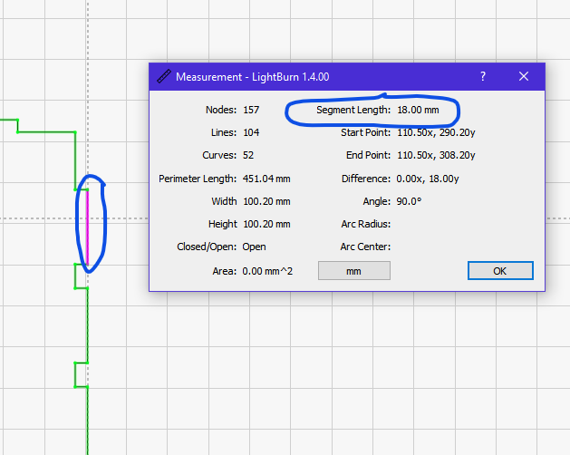
The figure entered here is multiplied by the thickness to give the required length rather than it being a target mm size. e.g. if the thickness is 3mm and you enter 2 into this entry box then the result will be 6mm (2x3mm), if you enter 6 then you’ll get 18mm…
I’ll try running some tests with a slightly different finger size. I’ll do the same with the spaces. I also measured the plywood and it’s exactly 3.3 mm. As you wrote, that alone would make a deviation, so I’m making it as accurate as possible. I leave the kerf to the Lightburn program. Thank you.
It doesn’t appear to be any wrong settings, two fingers are correct one finger is short.
I sometimes get “features” from Lightburn, but correct errors by hand and live with the slight imperfections.
If you cut that faulty box side again, does it repeat the error ? or is it a random error ?
Hi everyone
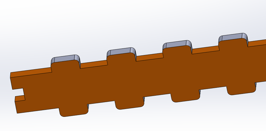
Ater getting frustrated with the finger feature I have tried to tackle the problem mathematically. I found it more convenient to go back to the original design in solidworks and fine tune it there. Then I converted the solids files to dxf and exported to lightburn, assigning 0 cutting settings for kerfs etc.
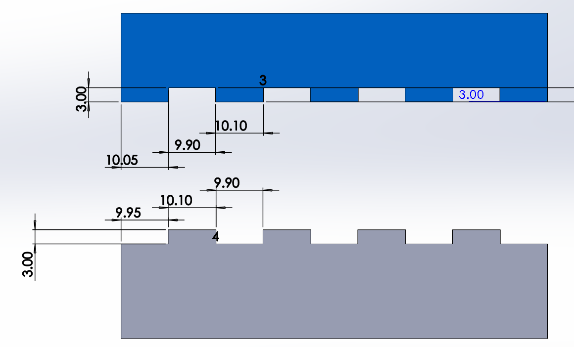
In order to determine the correct dimensions to each part, one should distinguish between the middle joints and the edge joints which seldom are the same.
Suppose you have a total length piece of 90 mm and the material thickness is 3mm. Let’s say that in order to achieve a tight fit you need a 0.2 mm difference between the male and the female and that you want the male finger to be 10.1 mm and the female 9.9 mm.
You’ll end having "middle joints and “edge joints”; substracting the total length of all the middle joints from the total length of the piece you will be able to calculate the size of the edges.
Piece 1 (in grey color): in this case we have female joints at the edges: you have 4 male fingers and 3 females in the middle, total: 70.1 mm. Substract from the total length: 90-70.1 = 19.9 . Divide 19.9 by 2 and you’ll get 9.95 which is the length of each of the two edge joints.
Piece 2 (in blue color): do the opposite: you’ll have a male finger at the edges now. You could calculate all dimesions like before, but it would be easier to calculate any given dimension substracting from 20. For example if the edge female joint in one piece is 9.95 the corresponding male one on the other piece will be 20-9.95=10.05 etc.
I usually like to add a 1.5mm fillet to the edges of the male fingers, which - without compromising the tightness of the fit - makes assembling easier and prevents chipping the adjacent piece in the way. Especially If you work with plywood.
I am newer to the laser community so I don’t play with the settings in Lightburn. I did a test that I found that measured the kerf settings so you can know the setting for your machine. I enter that setting, which is .070 mm for my machine, in the burn setting and it works for me. The test burn is called the burn test is the parts and samples section. You just set the cut setting for the material thickness as you would for a job and it will cut blocks that you can test to see what set fits and that gives you the burn setting. This might be a simple way but it works for me. Hope this helps.